
4 pole starter solenoid wiring diagram You will want an extensive skilled and easy to know Wiring Diagram. If it is a remote-mounted solenoid you must connect a control wire between the control circuit terminal on the solenoid and the cars ignition bypass terminal.
Basic Electricity Tutorial Relays
In mini cars equipped with small power starter the ignition switch start position is used to control the starter solenoid switch directly as shown in the picture below.
12v starter solenoid wiring diagram. Alternator relay wiring diagram starter the ultimate guide t x ignition switchcar solenoid definitive tractor motor starting system how it ford f250 fxe and horn interrupt amc forum circuit high diagrams 12v 1 3 typical car nissan second wire 1990 a club chopper forums questions upgrade help for b bos only yamaha 00 camaro chinese atv re or retrofit bypass. It reveals the parts of the circuit as streamlined forms and the power as well as signal links between the devices. Photo below shows the electrical connection end of the Lucas pre-engaged starter motor.
12v starter solenoid wiring diagram. Starter Solenoid Wiring Diagram 12v starter solenoid wiring diagram atv starter solenoid wiring diagram gm starter solenoid wiring diagram Every electrical structure is composed of various different pieces. The starter solenoid wiring diagram with starter relay shows in the following Fig.
Starter solenoid can only be operated with the ignition. 8N11500 Push Button Starter Switch Fits Ford Tractor 8N NAA 600 700 800 900 2000. 1973 Chevy Ignition Wiring Wiring Diagram Data Starter Solenoid Wiring Diagram.
Each component ought to be placed and connected with other parts in particular way. Starting control circuit with starter relay When the ignition switch has not turned to the start gear no current will passes through the relay coil and the starter relay contacts are open. Starter Bosch 0 986 023 530 Starterleistung 2kw Zähnez 11 10 Spannung 12v Jetzt Günstig Bestellen.
If not the arrangement will not function as it should be. John deere fuel solenoid bypass. 4 Pole Starter Solenoid Wiring Diagram.
Early production MGB use a starter solenoid triggered by post on the starter is used for connection of a number of Brown wires which In the diagram above the original starter switch is. For example if a module will be powered up and it sends out a new signal of fifty percent the voltage plus the technician would not know this he. Print the wiring diagram off plus use highlighters to trace the signal.
Freightliner starter solenoid wiring diagram. Each part should be set and linked to different parts in specific way. To properly read a wiring diagram one offers to know how the components within the method operate.
Inspirational Starter Relay Wiring Diagram Electrical Outlet 12V 12V Starter Solenoid Wiring Diagram. February 18 2022 Wiring Diagram. The diagram that comes with the part says the push button wire goes to the.
When you make use of your finger or perhaps the actual circuit with your eyes it is easy to mistrace the circuit. 12v starter solenoid wiring diagram Youll need a comprehensive professional and easy to understand Wiring Diagram. Jump them with another wire or a remote starter trigger switchthis is a tool if you.
April 17 2021 Wiring Diagram. Mercruiser starter solenoid wiring diagramMercruiser 470 intermittent no spark condition lots of diagnosis in thread boating forum. Wiring Diagram consists of several detailed illustrations that present the link of varied products.
You should have 12v at the post on the solenoid. 12v starter solenoid wiring diagram wiring diagram is a simplified tolerable pictorial representation of an electrical circuit it shows the components of the circuit as simplified shapes and the capability and signal friends amongst the devices. The solenoid isolator uses a continuous duty solenoid to connect the auxiliary battery during certain times like starting and charging then disconnects when not in use.
Shifnoid wiring diagram for a hurst quarter stick or a bm pro stick with a snfc or rc solenoid shift kit 87a 87a not used not used 14 inch gap 14 inch gap 12v to switched side of main battery disconnect switch 12v to switched side of main battery disconnect switchStarter Solenoid Wiring Diagram With Attached Solenoid Wiring. If not the arrangement will not function as it should be. This is how a 4-pole starter solenoid switch is connected.
The main difference between a 3-pole starter solenoid and a 4-point starter solenoid is how they work and how their connection to the field coil. It stands for the physical elements of the electrical circuit as geometric forms with the actual power and link links between them as slim edges. 1973 Chevy Ignition Wiring Wiring Diagram Data Starter Solenoid Wiring Diagram.
1Car Starter Wiring Diagram Non-Relay Control Type. With such an illustrative manual youll be capable of troubleshoot stop and complete your assignments with ease. As long as the neutral safety switch is in the park position or the clutch safety switch is closed the relay closes allowing voltage to flow to the starter solenoid.
12 Volt Winch Solenoid Wiring Diagram. So in the end it came to this. 12V 4 Terminal Starter Solenoid Wiring Diagram from static-cdnimageservicecloud.
Single Starter Relay Car Starter Wiring Diagram. 1 trick that We 2 to printing a similar wiring plan off twice. An example of a modern computer-controlled starter solenoid wiring diagram.
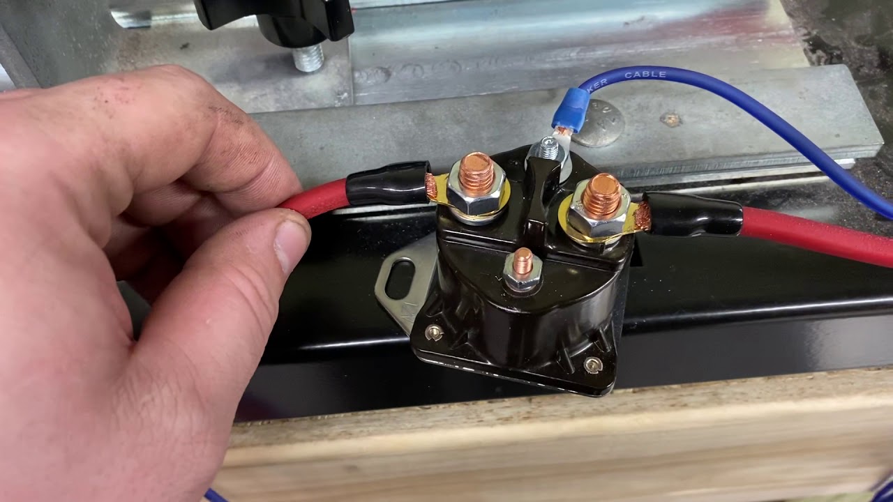
On the other hand in 3-pole solenoids the terminals primary function is to launch the starter motor. With such an illustrative guide you will have the ability to troubleshoot prevent and full your assignments without difficulty. To wire a 12-volt starter solenoid first disconnect the black negative cable from the vehicles battery and then connect the red battery cable to the large bolt on the solenoid.
Fuel Shut Off Solenoid for John Deere Replaces OEM M810324. It includes instructions and diagrams for different types of wiring strategies as well as other items like lights windows and so. This is a basic wiring guide and will not cover every application or scenario.
311006 12v Solenoid Wiring Diagram. One of the larger terminals is connected to the hot wire coming from the battery the second large terminal is connected to the starter the first smaller terminal S connects to the ignition switch the second small terminal connects to either ballast resistor R or ignition coil I and is generally unused. In 4-pole starter solenoids the four terminals speed up the motor.
12 volt winch solenoid wiring diagram You will want an extensive professional and easy to know Wiring Diagram. Otherwise the structure wont work as it should be. The solenoid then engages the starter to crank the engine.
Not merely will it assist you to attain your desired results faster but in addition make the entire. 12V Starter Solenoid Wiring Diagram 12 volt starter relay wiring diagram 12 volt starter solenoid wiring diagram 12v starter relay wiring diagram Every electric structure consists of various unique pieces. 12v starter solenoid wiring diagram.
With such an illustrative guide youll be capable of troubleshoot stop and complete your tasks without difficulty. 12v Starter solenoid Wiring Diagram. Alternative is find a wiring diagram for a MF35 that is 12v and follow along with that checking parts you have to know if they were swapped from 6v to 12v.
Reversing solenoid wiring diagram wiring library 12 volt winch solenoid wiring diagram. How To Wire A Starter Solenoid Diagram Wiring Diagram is the visual representation of a intricate electrical circuit.

