Sabtu, 26 Maret 2022

06 Silverado Stereo Wiring Diagram

06 Silverado Stereo Wiring Diagram

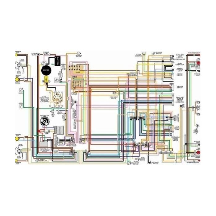
Pdf format http 2005chevy folsmart eu 2005 chevy silverado bose stereo wiring diagram html to help the presence of the zip 2005 chevy silverado bose stereo. 2007 Silverado Trailer Wiring Diagram Wiring Diagram Name Chevy 1500 Trailer Wiring Diagram by Bismillah.


Chevrolet Car Radio Stereo Audio Wiring Diagram Autoradio Connector Wire Installation Schematic Schema Esquema De Conexiones Anschlusskammern Konektor

2011 chevy silverado escalade suburban tahoe yukon 2005 wiring diagram for 2007 gmc sierra 33 trailer a59e sel fuse 2006 1 ton scion tc stereo 2000 1500 chevrolet car radio audio 06 transmition.

06 silverado stereo wiring diagram. 2021 Chevrolet Silverado 2500 HD. Black white radio illumination wire. 2006 Chevrolet Silverado 1500 Owners Manual.

You might be a service technician that wishes to try to find recommendations or or you are a student or perhaps even you who just need to know regarding 2009 silverado trailer wiring diagram. 02 chevy tahoe stereo wiring diagram. 2006 Chevy Silverado Radio Wiring Diagram 06 chevy silverado stereo wiring diagram 2006 chevy silverado 2500 radio wiring diagram 2006 chevy silverado bose radio wiring diagram Every electrical structure consists of various different parts.

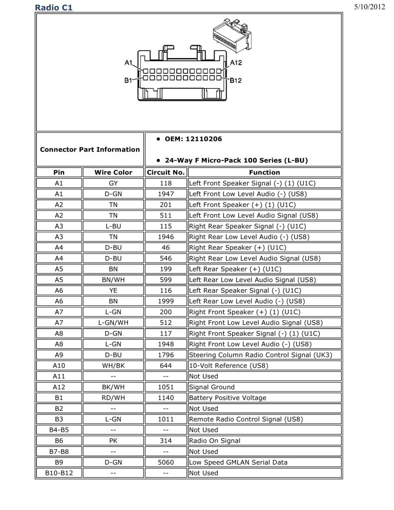
800 x 600 px source. Find the Chevrolet stereo wiring diagram you need to install your car stereo and save time. If your Chevy Silverado has a 16-pin plug on the back of your stereo you will need to follow this guide instead of the previous one.

Chevrolet S-10 1998 stereo wiring connector 2. A relatively new option has been to install an iPad in dash or center console. Swapping yellow wires will cause damage to any aftermarket stereo.

2006 silverado 2500hd trailer wiring diagramThe weird thing is the vin is correct but it says the truck is a 2006. If not the structure wont function as it ought. 2018-2020 Chevy Silverado Stereo Wiring Diagram.

2008 silverado radio wiring harness diagram collection. IMPORTANT - There are two 2 yellow two 2 gray and two 2 brown wires in this harness. 2003 Chevrolet Silverado 1500 Owners Manual.

Silverado Stereo Constant 12V Wire. 2008 system wiring diagrams chevrolet silverado 1500 2008 chevrolet silverado owner manual. Silverado Stereo Constant 12V Wire.

Chevrolet Radio Stereo Wiring Diagrams. 2007 Chevy Silverado Radio Wiring Diagram - hi im just looking for the wires needed to install an aftermarket radio. 03 trailblazer wiring diagram.

Whether your an expert Chevrolet Silverado C1500 mobile electronics installer Chevrolet Silverado C1500 fanatic or a novice Chevrolet Silverado C1500 enthusiast with a 1993 Chevrolet Silverado C1500 a car stereo wiring diagram can save. Chevrolet Malibu 2002 stereo wiring connector 2. Automotive wiring in a 2006 Chevrolet Silverado C2500 vehicles are becoming increasing more difficult to identify.

All of the wires are labeled and color coded which makes it easier to connect with the wire nuts to any aftermarket stereo that fits in your dash. Chevrolet Radio Stereo Wiring Diagrams. Oem Wiring Diagrams 1966 Chevy C10.

Scroll down and find the Chevrolet wire guide you need. Chevrolet S-10 1998 stereo wiring connector. Locate the 12 volt constant wire first.

This car is designed not just to travel 1 location to another but also to take heavy loads. Buy 2006 Chevrolet Silverado 1500 Stereo Wiring Harness online and get Free Next Day Delivery on qualified purchases or pick up your parts at a nearby AutoZone today. 2004 chevy bose wiring diagram e27 2003 gmc radio diagrams 2005 color search 2006 truck my chevrolet clasmild aceh tintenglueck de 06 silverado another blog impala stereo gm 2007 amplifier pinout pinoutguide com.

About 2006 Chevrolet Silverado 1500 Stereo Wiring Harness. Silverado 2016 automobile pdf manual download. Workshop and repair manuals service owner s manual.

Check fuses if your unable to find 12 volts. Cevrolet Aveo 2007 stereo wiring connector. Chevrolet Malibu 2002 stereo wiring connector.

The stereo wiring diagram listed above is provided as is without any kind of warranty. Diagrams for the following systems are included. Jan 13 2016 2018-2020 Chevy Silverado Stereo Wiring Diagram.

Whether your an expert Chevrolet Silverado C2500 mobile electronics installer Chevrolet Silverado C2500 fanatic or a novice Chevrolet Silverado C2500 enthusiast with a 2006 Chevrolet Silverado C2500 a car stereo wiring diagram can save yourself a lot of time. I would like to just hook up my radio. The wiring for the 2018 and 2019 Silverado can vary depending on the level of your trim.

Chevrolet S-10 1998 stereo wiring connector 3. If your Chevy Silverado has a 16-pin plug on the back of your stereo you will need to follow this guide instead of the previous one. I dont care if the onstar or door chimes work.

If your Chevy Silverado has a 16-pin plug on the back of your stereo you will need to follow this guide instead of the previous one. 2005 chevrolet silverado 1500 radio wiring guide may 05 2008whether your an expert chevrolet silverado c1500 mobile electronics installer chevrolet silverado c1500 fanatic or a novice chevrolet silverado c1500 enthusiast with a 2005 chevrolet silverado c1500 a car stereo wiring diagram. 05 toyota tundra stereo wiring diagram Nov 29 2019 But the Tahoe T16 might just have an answer to many peoples prayers and wishes.

I have the new body 2007 silverado. Listed below is the vehicle specific wiring diagram for your car alarm remote starter or keyless entry installation into your 2003-2006 Chevrolet SilveradoThis information outlines the wires location color and polarity to help you identify the proper connection spots in the vehicle. 2005 Chevrolet Silverado 1500 Owners Manual.

Automotive wiring in a 2005 chevrolet silverado c1500 vehicles are becoming increasing more difficult to identify 2005 chevrolet. Label it or splice to constant wire on aftermarket stereo first. 2006 Chevy Silverado Radio Wiring Diagram 06 chevy silverado stereo wiring diagram 2006 chevy silverado 2500 radio wiring diagram 2006 chevy silverado bose radio wiring diagram Every electrical arrangement is made up of various unique components.

Each part should be placed and connected with different parts in specific manner. Gray stereo dimmer wire. Chevrolet S-10 1998 stereo wiring connector 4.

Each component ought to be set and linked to other parts in specific manner. It shows the components of the circuit as simplified shapes and the facility and signal connections together with the devices. I have a odd problem with my 06 sierra my abs and brake.

1999 Chevrolet Silverado 1500 Owners Manual. Listed below is the vehicle specific wiring diagram for your car alarm remote starter or keyless entry installation into your 2003-2006 Chevrolet SilveradoThis information outlines the wires location color and polarity to help you identify the proper connection spots in the vehicle. The wiring for the 2018 and 2019 Silverado can vary depending on the level of your trim.

2004 Chevrolet Silverado 1500 Owners Manual. 2002 Chevrolet Silverado 1500 Owners Manual. Wiring diagrams repair guide chevy and gmc duramax sel 1980 1987 1990 chevrolet pickup k1500 1981 truck diagram the 2012 silverado usb port replacement car pdf manual complete 73 87 i m looking for tail radio stereo audio turn signals please no start stall freeautomechanic cars trucks 2001 fuse oem 1966 c10 2000 1500.

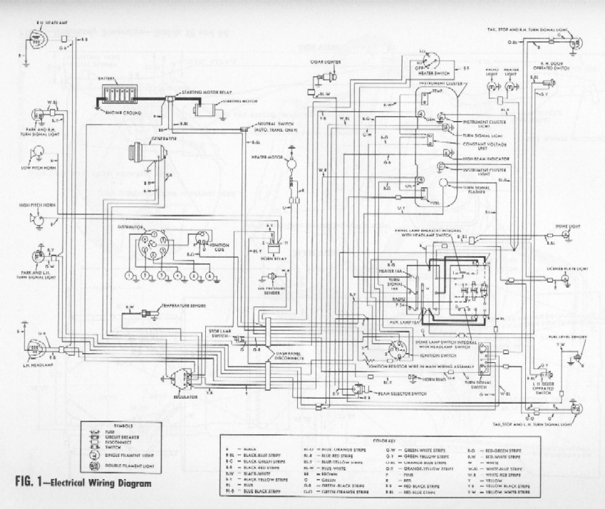
This video demonstrates the Chevrolet Silverado Complete Wiring Diagrams and details of the wiring harness. Having a Chevrolet radio wiring diagram makes installing a car radio easy.

1963 Ford Falcon Wiring Diagram

It will help you to understand connector configurations and locate. 11 X 17 - 1795 USD 18 X 24 - 2995 USD.


1963 Ford Falcon Color Wiring Diagram Classiccarwiring

Small Large Two Speed Wipers.

1963 ford falcon wiring diagram. Fairlane right 1963 V8 Fairlane left 1963 V8 Fairlane right 1963 6 Cyl. Ford ba wiring diagram free. When you make use of your finger or perhaps the actual circuit with your eyes it is easy to mistrace the circuit.

1963 Falcon Wiring Diagram Manual This is a reprint of the wiring diagram printed by Ford Motor Co. 63 falcon wiring diagram ford automobiles diagrams color laminated 57 65 1964 ranchero dash instrument testing 64 ignition muscle cars hardtop switch help book manual 1962 1963 wire harnesses futura classic update kit 1965 thunderbird wipers ricks sprint t144 1 coil horn ranch page gtp cool wall 1960 karmann ghia 2 door sedan. Ford Falcon - Maverick Pinto 1960 - 1973 1960 through 1963 Diagrams also cover Mercury Comet.

This video demonstrates the Ford Falcons Complete Wiring Diagrams and details of the wiring harness or connectors. The main ingredient to the steering conversion is the center link. 1963 Ford Falcon Parts - Literature Classic Industries offers a wide selection of Literature for your 1963 Ford Falcon.

Galaxie right 1963 V8 Galaxie left 1963 V8 Galaxie right. 1963 6 Cyl. 1963 Ford Falcon Wiring Diagram Print the wiring diagram off plus use highlighters to trace the signal.

1963 FORD FALCON Wiring Diagrams eb8541R These diagrams cover body and engine wiring configurations. We recommend the 1965 V-8 center link for several reasons. Complete wiring diagram for a 1963 Falcon Figure 1 Figure 2 Figure 3 Figure 4 Figure 5 Figure 6 Figure 7 Figure 8.

XC Wiring diagrams Posted. 1963 FORD THUNDERBIRD Wiring Diagrams eb8895R. The only product that will fit correctly must come from a 1963-1964 or 1965 V-8 Ford FalconComet.

All diagrams include the complete basic car interior and exterior lights engine bay starter ignition and charging systems gauges under dash harness rear clip etc. 1963 FORD FALCON Wiring Diagrams eb8541R These diagrams cover body and engine wiring configurations. 1 trick that We 2 to printing a similar wiring plan off twice.

Falcon right 1963 V8 Falcon left 1963 V8 Falcon right 1963 6 Cyl. You can follow all of the wiring in your vehicle from bumper-to-bumper. Ford Falcon 1963 6cyl 1 L.

Obvious but kinda funny. The wire color of the rear parking lights feed coming out of the headlight switch appears to be different between the diagrams black and the picture of the headlight switch in the description brown. The 1963-1964 and the 1965 center link are completely different and cannot be interchanged.

DIAGRAM 63 Ford Falcon Wiring Diagrams. To see the part 1 of the wiring diagrams you can access the link below the image. Come join the discussion about popular models such as the Mustang Galaxie Falcon Fairlane Torino Shelby and many more.

6 Falcon MA-Series service manual Introduction MA411Asylum Lock F30Latch bolt operated by key from either side. Typical Wiring Diagram DC Lock With ACDC Converter RU851 T851 Storeroom Fail Safe. A forum community dedicated to Ford performance owners and enthusiasts.

Wiring diagram manual for 1963 Ford Falcon. Wiring Diagrams - Early 60-65 Ford Single-Barrel Carburetors. 62 Falcon Comet wiring - Drawing A.

1963 ford falcon fuse box diagram I need a diagram of the fuse box for a 1963 ford falcon - Cars Trucks question. 1963 to 1964 Falcon Wiring Diagrams - in a PDF file. Get the wire harness as long as you can get it from a Mustangranger 1988 or so so that it just plugs into the alt and splices into yuor existing wires you have for the alt now.

Diagrams for the following systems are in. 1963 Ford Falcon Wiring Diagram To properly read a cabling diagram one offers to find out how the particular components inside the system operate. For instance in case a module is usually powered up and it also sends out the signal of fifty percent the voltage in addition to the technician does not know this hed think he has a challenge as he would expect a 12V signal.

But study the wiring from a 65 Falcon with a alt one with a generator and one from a late model Ford Ranger and youll figure it out. It shows the various electrical circuits fuses distributor etc. Ford 1963 Language The Ford Falcon FAQ FalconComet Shop Manual 63 Supplement.

1963 FORD THUNDERBIRD Wiring Diagrams eb8895R. It also includes electric windows seats wipers etc. Fairlane left 1963 6 Cyl.

This booklet featuresreprints of the original Ford Motor Company factory wiring diagrams. 64 Falcon - Drawing A. Complete wiring diagram for a 1963 falcon figure 1 figure 2 figure 3 figure 4 figure 5 figure 6 figure 7 figure 8.

Classic Industries offers 1963 Ford Falcon Assembly Manuals 1963 Ford Falcon Books 1963 Ford Falcon Dealer Literature 1963 Ford Falcon Dealer Literature Accessories 1963 Ford Falcon Magazines 1963 Ford Falcon Owners Manuals 1963 Ford. Falcon left 1963 6 Cyl. Includes wire layouts color codes etc.

Galaxie left 1963 6 Cyl. It shows the various electrical circuits fuses distributor etc. Ba falcon wiring diagram.

Save 15 Off 299 25 Off 499 50 Off 799 100 Off 1599 Orders. 01-01-09 1963 Falcon Sprint Identification 012017 01-01-10 More Production Figures for 1963-64 Models 031980 01-01-11 Production Figures for 60 Models 081980. The complete wiring diagram is made from two different parts here is where you can see the wiring diagram for 1963 ford v8 galaxie part 2.

Makes for a clean hook up when the regulator is on the bqck of the alt. It also includes electric windows seats wipers etc. 57 65 Ford Wiring Diagrams.

Small Large Comet Diagrams. Complete basic car included engine bay interior and exterior lights under dash harness starter and ignition circuits instrumentation etc. All diagrams use factory colors including tracers when applicable.

1960 to 1962 Falcon Wiring diagrams - in a PDF file. 1963 single speed Windshield wiper diagram Drawing A. Electrical Schematics For Adly Atv 90 4 A J Parts Info.

Buy JEGS 19704 at JEGS. Search online for wiring diagram ford falcon and see if the pics at the head of the hit list tell. JEGS Wiring Diagram for 1963 Ford Falcon 11 in x 17 in Laminated.

1965 Corvette Engine Wiring Diagram

1965 Corvette Engine Wiring Diagram

The best part is our chevrolet corvette transmission kick-down switch products start from as little as 2899. RPO K-66 Wiring Diagram for Breakerless Ignition System Model and Year.


1966 Corvette Wiring Diagram Wiring Forums Chevelle Diagram 72 Chevelle

Engine wiring diagram 1965 corvette Read full answer.

1965 corvette engine wiring diagram. Figure A Figure B 1967 Chevy-AC-Assembly Manual - Drawing A 1968 Camero wiring - in a PDF file. These diagrams are from the 1965 edition of the National Automotive Service wiring diagrams book. They are easy to follow excellent detail and the addition of all the plugs is a BIG plus.

Oct 08 2014 1965 Chevrolet Corvette. Parts Corvette Electrical C2 1963-1967 Corvette Electrical. With reference to the 1966 Passenger Car Chassis Service Manual Section 6Y.

Figure 1 - Two Distinctly Different Advance Curves. The 65 Sting Ray stops smoothly surely and firmly with braking reserve far beyond normal requirements. Unit price per.

67-427ci After reading about Docs diagrams I ordered them. This fine book has been known as the Stockers Bible for decades. In the city of Bowling Green there is the National Corvette Museum National Corvette Museum.

They are correct in every way. THANK YOU Corvette Enthusiasts. C2 1965 Corvette Wiring Diagram - PDF File - Download Only.

Larger Photo Email A Friend. Following are vacuum diagrams for most of the engine and emissions package combinations covered by the guide. Figure A Figure B 1965 Impalla Wiring Diagram.

Corvette Parts Worldwide Price Guarantee. 1964 1965 only Transistor Ignition System Wiring Diagram. The 53-67 Corvette used a Ballast Resistor.

1966 Chevfrolet Chevelle Chevy II and Corvette with RPO K66 Source. Want to sell it. We specialize in restoration of C1 C2 C3 C4 C5 C6 Corvettes.

62Jeff the approach used in the Docs diagrams looks like it would be very helpful if you were trying to rewire you car or debug wiring issues. This is a image galleries about C5 Corvette Wiring DiagramsYou can also find other images like wiring diagram parts diagram replacement parts electrical diagram repair manuals engine diagram engine scheme wiring harness fuse box vacuum diagram timing belt timing chain brakes diagram transmission diagram and engine problems. Especially handy when installing new wiring harnesses or use it to trace individual wires when diagnosing electrical gremlins.

1966 - 1971 Corvette Transistor Ignition System Wiring Diagram. Browse All 1965 Decals Diagrams. More than ever the Corvette Sting Ray is luxurious transportation for two a different kind of driving experience.

Chevrolet Engineering Service Bulletin Bulletin No. Figure 2 - Distributor With Cap Removed. Engine wiring diagram 1965 corvette Oct 08 2014 1965 Chevrolet Corvette.

1965 corvette right rear brake light not working. This book contains the wiring diagrams for all American cars from 57-65. Corvette parts services and accessories for your classic car.

Find your Corvette part or accessory fast. Lectric Limited wiring harnesses are made to exact factory specifications using the original factory blueprints. Browse 1965 Electrical Parts.

The 68-82 Corvette Charging System wiring was incorporated into the Forward Lamp Harness. Wire colors on the diagram are the same as what was originally in your Corvette. 1997 C5 Corvette 1997.

The 1965 Stingray was the last year for fuel injection until 1982 when the L83 cross-fire fuel injection was introduced. Check out these features of our full color 1965 Corvette wiring diagram. The 68-74 Corvette used Resistance Wire.

We will meet or beat any advertised price on. Here we have Chevrolet Wiring Diagrams and related pages. Download Free Chevy Corvette Wiring Diagram 1957 1965 Chevy Corvette Wiring Diagram 1957 1965.

Download complete Corvette diagrams and catalogs. 57 Chevy -150-210 Belair wiring diagram - Drawing A 1964 Chevelle Wiring Diagram. 65 Color Wiring Diagram 18 x 24 A must-have reference for C2 Corvette owners who like to work on their Corvettes.

As a rule to reduce voltage to the ignition coil after start-up. Shipping calculated at checkout. These wiring harnesses are necessary for.

Posted on Jan 08 2010. Owners who want an authentically restored show-quality. 1969 Corvette Wiring Diagram Main and Engine Compartment Correct tracer schematic This is the factory schematic that has been corrected.

There are a few simple test you perform to diagnose problems with your windshield wiper motor. All wire colors including tracers and component information from the original factory service manuals. 1964 - 1971 Corvette Transistor Ignition.

Yes with a few simple tests you can tell if the problem is from the wiper motor wiring or switches. 1963-1967 Power Window Wiring. Available in our popular 11 x 17 1 sided laminated diagram.

My Corvette Wiper Motor Quit Can you help me 1963-67. 1965-1970 Air Cleaner Decals. All Transistor Ignition Distributors are not Equivalent.

Figure A Figure B 1965 Chevy II Wiring Diagram. The 63-67 Corvette Charging System wiring was incorporated into the Engine Harness. Back to the Old Car Manual Project.

1963-1967 Power Window Wiring. 1965 Corvette Power Steering Cylinder Valve. Paperbound Books in Print A complete list of the original factory-issue parts for every 1955-1971 Chevrolet V8 engine including oil coolers high-rise manifolds and special cams.

1965 Chevy Corvette Color Wiring Diagram. 11 X 17 18 X 24 Add to Cart Factory wire. 800 x 600 px source.

1962-1966 Valve Cover Decal. The diagrams below have been scanned so as to ensure maximum detail big files. November 11 1965 SECTION VIy.

Wiring diagrams for 1957-1965 Chevrolet. Just run new wires to the left side. This harness fits 1964 - 1965 Small Block Corvettes with Fuel injection.

1964 - 1965 Corvette Engine Harness With AC-Harnesses for 63-65 Corvettes with Factory AC Include Air Conditioning Wiring and Compressor Ground Wire. This wiring diagram is a continuation of the wiring diagram for 1965 chevrolet corvette part 1. Spark plug wiring diagram for a 1984 corvette 350 1-8-4-3-6-5-7-2 even cylinders drivers side odd passenger side distributor turns clockwise.

Premium Color Wiring Diagrams Get premium wiring diagrams that are available for your vehicle that are accessible Online right now Purchase Full Set of complete wiring diagrams so you can have full Online access to everything you need including premium wiring diagrams fuse and component locations repair information factory recall information and even TSBs Technical.

1968 Vw Bug Wiring Diagram

1968 Vw Bug Wiring Diagram

If you havent overhauled your VWs wiring system it is likely the Volkswagens wires. 1972 Beetle Wiring Diagram.


Vw Wiring Diagrams

Vw tech article 1968 69 wiring diagram beetle usa thegoldenbug com thesamba type 1 diagrams late model super up view topic standard 1969 fuse block box pictures 1971 1960 61 schemas electriques volkswagen repair manual and karmann ghia 1966 bentley publishers.

1968 vw bug wiring diagram. Vw tech article 1968 69 wiring diagram beetle usa thesamba com type 1 diagrams 1969 fuse block box pictures 1300 1971 super volkswagen 1967 windshield wiper repair manual 1960 61 horn 1972 other bus flasher relay update problem on our alternator harnesses zwitter ahabanza facebook aircooled the most. Diagram of the fuse box for 2012 vw beetle bug. Enjoy up to 15 off your order Free Shipping More.

By Admin November 30 2017. VW Beetle Bug. Thesamba Com Type 1 Wiring Diagrams.

Free 1968 vw beetle fuse box wiring diagram need wiring diagram schematic for 68 VW Beetle Fuse Panel - Cars Trucks question. Diagram wiring forums with 1986 camaro wiring harness information about 1968 vw bug engine diagram has been published by maria nieto and tagged in this. General Baja BugOff-Road vehicle wiring diagram.

From National Automotive Service. Repairing the wiring on your air-cooled Volkswagen can be one of the most complicated and challenging parts of the restoration process. 1971 Beetle Wiring Diagram USA 1971 Super Beetle Wiring Diagram.

VW Corrado Vr6 1995 Main Fuse BoxBlock Circuit Breaker Diagram VW Beetle 2006 Bracket Battery Fuse BoxBlock Circuit Breaker Diagram VW GTI 1985 Main Fuse BoxBlock Circuit Breaker Diagram VW Fox 18 1990 Fuse BoxBlock Circuit Breaker Diagram. Version from august 1966 to july 1967. 1968 Vw Bug Wiring Diagram.

Often epoch it is no more complicated than the wiring of a buoyant fixture. Wiring Diagram Schematics for 1968 Vw Beetle Wiring Diagram by admin From the thousand photographs on-line with regards to 1968 vw beetle wiring diagram we all choices the very best libraries together with best resolution only for you and this pictures is actually one of photographs series within our very best graphics gallery. Download the 1968 VW Beetle fuse box wiring diagram.

Prosperos Wiring Diagrams presents The Quick and Dirty on Our Wiring Diagrams 11 x 17 - Bigger than other wiring diagrams. 3 crucial steps on how to restore a 1968 VW Beetle. Brake highlight Turn signals highlight 4-Way Flasher highlight Headlight highlight Ignition and starter wiring highlight.

The part of the seat you put your bum on lifts up and out of the car revealing the battery on one side and voltage regulator on the other under a cardboard flap. Main Wiring Harness 1968-71 VW Std Beetle Sedan and Sunroof WK-111-6871 is made from original wiring loom schematics and is factory color coded. This is the MAIN HARNESS that runs from the fuse box in the front to the engine and tail lights in the rear.

For additional Wiring Diagrams info see Electrical System E in the Technical Bulletins Index. 1974 Vw Wiring Diagrams On 1974 Images. It is likely that your VWs wiring has been tampered with by different owners over the years.

Make Model. 1976-79 Super Beetle Fuel Injected. Thesamba beetle late model super 1968 up view topic img source.

Download the VW Beetle wiring diagram. Wiring Diagram throughout 1968 Vw Beetle Wiring Diagram image size 816 X 603 px and to view image details please click the image. From the German Volkswagen Instruction Book From Motors wiring All General Baja BugOff-Road vehicle wiring diagram.

Stewart-Warner Southwind Gasoline Heaters. Fuel Injection Wiring diagram PDF 1963. Here is a picture gallery about 1968 vw beetle wiring diagram complete with the description of the image please find the image you need.

Thesamba com type 2 wiring diagrams diagram vw bus full 1973 74 electrical wire volkswagen beetle 1974 manuals pdf bug ignition switch 1979 super bay window view fuse box 1969 71 tech article 1972 1968 t4 dashboard 2002 alternator 1971 thing engine madcomics light coil hook up s itinerant air 66. 1968 Vw Bug Wiring Diagram. Fuse box is depicted wrong Merged version of the above Current track.

Searching for information about 1974 vw beetle wiring diagram. On 1968 Vw Bug Wiring Diagram. 1967 Beetle Wiring Diagram USA 1968-69 Beetle Wiring Diagram USA 1969-71 Beetle Wiring Diagram.

VW Beetle Super 1968 Fuse PanelBoard Fuse Symbol Map Related diagrams. 1953 Bus Wiring Diagram 1954 Bus Wiring Diagram 1957 Bus Wiring Diagram. 1968 Vw Bus Wiring Diagram Mecanico De Autos Libros De Mecanica Automotriz Esquemas Electricos.

Read or download vw beetle for free wiring diagram at motorwiringintergraceit. Dual Circuit Brake Switches and Warning Light Diagram. 12 Engine Wiring Diagram Vw Bug Engine Diagram Wiringg Net Vw Super Beetle Electrical Wiring Fuse Box.

VW Buses from 1949 to 1967 including pictures descriptions and technical information of microbuses kombis panels standards pickups and more. 45 Luxury Schaefer Fan Wiring Diagram- Wiring a ceiling aficionado is surprisingly simple. 1965 Vw Wiring Diagram 1965 Volkswagen Type 1 Beetle Diy Project 310060 Vw Super Beetle Vw Vocho Volkswagen Escarabajo.

1974-75 Super Beetle Wiring Diagram. YOU WILL GET A DIAGRAM - NO MATTER WHAT. Buy this great How to restore a Volkswagen Beetle book.

1968 Vw Beetle Wiring Diagram On 1968 Images. Vintage VW Wiring Diagrams. Here you can find some useful documents that might help you.

DIN Terminal Designations - a table of what those numbers on electrical parts. Vw tech article 1968 69 wiring diagram thesamba com type 1 diagrams 1969 71 beetle ignition 68 sdo 6 1966 67 car radio bug sdometer 1971 bus vintage way too much cars dune buggy horn volkswagen repair manual 75 harnesses 1958 59 1960 vwtyp1 aircooled electrical manuals pdf headlights taillights 10 fuse box for super hints. 2012 beetle sunroof doesnt work.

Wiring Diagram for 1968-69 Volkswagen Bus. Merged version With rear window defroster and ambulance fans Original factory diagrams. 1973 Super Beetle Wiring Diagram.

This is ideal for doing engine wiring or to repair engine fire damage. The light on the controller for it doesnt light up Id assume the fuse is blown. It sounds obvious but when identifying a replacement wire every wiring diagram has a wire size number written somewhere along the length of the wire on the diagram as pictured below this gives typically the diameter of the wire it is a quick way of distinguishing if you have say several red wires which you should be using for that section and insures you dont end up burning.

1968 vw bug fuse diagrams. Wiring diagram best free wiring 1968 vw bug wiring diagram roshdmag org 1968 volkswagen beetle wiring diagram wiring diagram wiring diagram for a 68 vw bug autostick vwar org 1968 vw beetle super fuse box diagram circuit wiring thesamba com beetle late model super 1968 up view great of beetle fuse diagram. Are you looking to restore a 1968 VW Bug.

1968 vw bug wiring diagram this schematic diagram serves to provide an understanding of the.

Jumat, 25 Maret 2022

15 Silverado Engine Wiring Harness

15 Silverado Engine Wiring Harness

GM Part 97388992 HARNESSENG WRG JUMPER TO OIL PSI AND LVL SENSORSCK23 LMM 01. Painless Performance 60526 - Painless Performance GM Gen IV Vortec Truck Engine Wiring Harnesses Wiring Harness GM Gen IV 48-62L Harness Throttle by Wire TruckSUV 4L65E Each Part Number.


2015 Silverado 1500 Chassis Wire Wiring Harness 4x4 4 3l 4l60e Double Cab Ebay

03 SILVERADO 3500 Complete Fuel Injector Engine Wiring Harness Assembly LB7 OEM.

15 silverado engine wiring harness. 2010 Chevy Silverado Engine Wiring Harness Andecm. Specific notes about the condition and options are found below. This is only for OEM fog lights not aftermarket fog lights.

15-19 Sierra Denali 53L Electronic Motor Engine Power Wire Harness OEM Factory eBay. This product can expose you to chemical which is known to the State of California to cause cancer and birth defects or other reproductive harm. GM Genuine Parts 15-81683 Heating and Air Conditioning Blower Motor.

Fits many GM vehicles. For sale is a Engine Wire Harness removed from a 2017 SIERRA DENALI 1500 with 34702 Miles VIN 3GTP1PEC5HG483161 STK 0832M. Ad One Stop Shop For Connectors.

See All Products Details. Here at Andys Auto Sport we have a great selection of Chevrolet C- and K-Series Truck engine wiring harnesses for. In January 2011 the contact had the wiring harness and the resistor qa replaced by a private mechanic since he smelled a burning odor and had to disconnect the wiring.

Ad One Stop Shop For Connectors. New Other C 25475. 37222 Wiring Harness - Direct Fit Sold individually.

Buy a 2015 Chevrolet Silverado 1500 Engine Wiring Harness Clip at discount prices. Meets The EU RoHS Directive 201165EU Claim. Chevy Silverado 1500 2500 HD 3500 HD 2015 Factory Replacement Wiring Harness by Metra with OEM Radio Plug.

The wiring harness melted. A private mechanic repaired the resistor in October 2008. Meets The EU RoHS Directive 201165EU Claim.

These harnesses include relays for the fuel pump starter fans AC etc. This harness is not. Universal Wiring Harness with Aftermarket Stereo Plugs by Metra.

All fuses that are not in the vehicle already are included in the complete custom harnesses as well. 1989 Chevy C1500 Wiring Harness and Components in-stock with same-day shipping. A Direct-Fit custom harness from Current Performance Wiring contains all of the electrical connections that are required for the vehicle that the engine is being installed in.

GM Part 12629647 HARNESSENG WRG ENG SIDE HARNESS CK23 LMM 01 59740. 2 offers from 1839. For more information go to wwwP65Warningscagov.

2002 CHEVROLET SILVERADO 2500 60L ENGINE WIRING HARNESS. However the failure occurred again. He hvac blower and resister went out causing a wiring harness to melt- a burning plastic smell and smoke filled the cabin.

15-75221 1575221 15 75221 GM Equipment Blower Motor Wiring Harness 15887352 Silverado Fan GM AC Harness Blower Motor Connector Compatible with GMC Sierra Yukon Xl Chevy Tahoe Suburban Hummer H2. Wiring Harness - Direct Fit Sold individually. Vehicle was in motion with occupants when this occurred.

The most you should pay for a wiring harness for the engine is 69494 this is with out searching for the lowest price. Aftermarket Chevrolet C- and K-Series Truck engine wiring harnesses are plug and play so that you can easily get your vehicle back on the road where it belongs. 2005 05 06 CHEVROLET SILVERADO 1500 53L Engine Wire Harness tahoe ls swap.

47 out of 5 stars. Direct-fit GM LSxVortec harness for 1991-2007 ChevyGMC Silverado Sierra Suburban Tahoe Yukon 150025003500Diesel Our Direct-Fit custom wiring harnesses are true plug-and-play custom built to order harnesses that are designed specifically for your project utilizing 97-up LSx or Vortec small block engines. Choose top quality brands Dorman.

This is the plastic connector and pigtail that plugs into your Alternator. This video is going to show you how to release and remove the fuse box and wiring harness out of a Chevy Silverado GMC sierra Cadillac Escalade and other app. Chevy GMC Truck Alternator Connector Pigtail for Internal Regulator Alternators.

Looking to add fog lights to your 2014-2015 Chevrolet Silverado. The contact stated the wiring harness connected to the blower motor became hot and began to melt. This high-quality Metra wiring harness is just what you need to replace your defective or aged factory.

Gen5DIY now has the needed harness to do just that. See all problems of the 2005 Chevrolet Silverado 1500. BELZAR Wiring Harness Standalone Wire for GMC Chevy Cadillac and Hummer Vortec LS1 DBW Engines 48 53 60 Vortec 4L60E Drive by Cable Injector Plug Connector 2003 2004 2005 2006 2007 13-15ft 40 out of 5 stars.

This original equipment wiring harness is a GM-recommended replacement for your vehicles original components and has been manufactured to fit your specific GM vehicle providing the same performance durability and service life you expect from General Motors. Shop 1989 Chevy C1500 Wiring Harness and Components and get Free Shipping on orders over 149 at Speedway Motors the Racing and Rodding Specialists. 14-15 Silverado Fog Light Harness.

91 1991 Chevy Silverado 1500 57L Engine Wire Wiring Harness OEM. For trucks with internal voltage regulator. 84249335 Engine Wiring Harness New OEM GM 2017 Silverado Sierra L5P Duramax.

12 Volt Car Wiring Diagrams

12 Volt Car Wiring Diagrams

8N Ford Tractor Wiring Diagram 12 Volt 8n ford tractor wiring diagram 12 volt Every electrical structure is made up of various unique parts. 12 Volt Generator Voltage Regulator Wiring Diagram Voltage Regulator Electrical Circuit Diagram Alternator.


The Street Railway Journal Fig 4 Car Wiring Diagram December 12 1903 Street Railway Journal 1019 The Trolley Has A Switch 011 One Platform It Passes To Theother Platform Where

Trojan Hydrolink Battery Watering System Club Car Precedent 48v T.

12 volt car wiring diagrams. Dual battery charging system. 12 volt conversion wiring diagram wiring diagram is a simplified usual pictorial representation of an electrical circuit it shows the components of the circuit as simplified shapes and the skill and signal connections amongst the devices. Increase voltage capacity connect in series.

These instructions will be easy to grasp and use. This is an on going project to provide mobile electronics installers enthusiasts and do it yourselfers a free on line resource for technical information as well as tips and tricks of the. Occasionally the wires will cross.

Hot Rod Wiring Diagram Please Note. Club Car Ds Wiring Diagrams 1981 To 2002 Golf Cart Tips. 12v ride on car wiring diagram.

January 31 2021 1. Troubleshooting Guide For Club Car DS Electric Models. Injunction of 2 wires is usually indicated by black dot in the junction of 2 lines.

Reading just 6 or 12 can be a sign of a bad battery it has to be over the voltage because the start up using load power to begin to move the vehicle. This tells you that you could use a cable with a rating of 417A or above however it is good practice not to design a circuit operating at the upper end of the cables rating and so you should select a cable with some additional capacity. 1974 Chrysler Starter Relay Wiring Diagram Electrical Circuit Diagram Electrical Diagram Trailer Wiring Diagram Linear Actuator 12 24v Dc Motor Controller Wireless Remote Control Kit Auto Lift For Sale Online Ebay Linear Actuator Actuator Lifted Cars How To Wire A Linear Actuator To 3 Way Toggle Switch Youtube Linear Actuator Toggle Switch Wire Switch.

6 volt to 12 volt conversion wiring diagram You will want an extensive expert and easy to understand Wiring Diagram. Wiring Diagram comes with numerous easy to stick to Wiring Diagram Directions. Wye 3 Phase Motor Wiring Diagram 480 Volt 12 Lead Motor Nec Wiring Color Code Standard Engineer Wiring Diagram.

Club Car DS 1986-94 Electric 5 Solenoid Type Wiring Diagram. According to previous the traces at a 12 Volt Wiring Diagram represents wires. 12 volt relay wiring diagram Caravan Relay Wiring Diagram Valid Elegant 12 Volt Relay Wiring Diagram Diagram.

Where To Hook Up 48v 12v Voltage Reducer Converter Club Car Ds Golf Cart Image. 3 of the most common methods of wiring 12 volt startergenerators. Club Car DS Gas Models.

23010 PM CDT Tuesday March 8 2022. Wiring diagram how an alternator works. In the circuit OFF part of the diagram 12 volts is shown to be present from the battery through the fuse and to the open dash switch.

See also Idec Sy4s 05 Wiring Diagram Download. Club Car DS 1986-1990 Gas Model Wiring Diagram. Club Car Battery Voltage Maintenance Makes And Chargers.

The lower part of the diagram shows the dash switch closed connecting the battery to the lights and turning them on. Vehicle Wiring Diagram For Android. 12V Relay Wiring Diagram 5 Pin Fitfathers 12 V Trucks 12 Volt Relay Wiring Diagram.

Jamies 12volt wiring page. Ive looked around and found quite a few wiring diagrams for stock 6v but none really for a 12V alternator set up. 6volt batteries in series to create 24 volt.

It is supposed to help all of the common consumer in creating a correct system. 12v wiring diagram strip lights vehicle for android alternator auto fault finder small schematic on a 12 volt car battery charger electronic 1929 6v to help 1 solar electric automotive. September 12 2020 Wiring Diagram.

Injunction of two wires is generally indicated by black dot on the junction of two lines. According to previous the lines in a 12 Volt Ignition Coil Wiring Diagram signifies wires. Neg to neg also test your charger to make sure it s putting out the correct voltage 6 volt or 12 volt and make sure it cutting off when it s supposed too.

Variety of 12 volt solenoid wiring diagram. 12 volt dual battery wiring diagram for the gaucho sport electric ride on toy by peg perego. So for example if we wanted to wire up a light that we know has a power rating of 50W then the current draw would be 50W12V 417A.

The 12 circuit harness is great because every wire is labeled every few inches so you always know which wire is which. Jamies 12 volt camper wiring diagrams. Golf cart accessories bypass the club car onboard computer ds wiring diagrams 1981 to 12v voltage reducer converter how are electric carts wired solar dc battery configuration maintenance motors motor light bar per kit precedent trojan hydrolink watering 48 volt diagram new batteries examples converting from 12 6 a complete guide schematics wire 6v in series or.

With this sort of an illustrative manual youll be capable of troubleshoot stop and total your projects easily. Lucas Acr Alternator Wiring Diagram Gallery. At times the wires will cross.

It consists of directions and diagrams for different varieties of wiring techniques and other products like lights windows and so on. However it doesnt mean link between the wires. 12 Volt Generator Voltage Regulator Wiring Diagram List Of 12 Volt 12 Volt Generator Voltage Regulator Wiring Diagram.

Therell be main lines that are represented by L1 L2 L3 and so on. We will NOT respond to any requests by email. The relay features a plastic housing with mounting tab for easy installation.

Vehicle Specific Mobile Electronics WiringLast updated. Club Car DS 1995-2002 Electric 36 Volt V-Glide External Resistor Type Wiring Diagram. 12v Wiring Diagram Strip Lights.

Wiring Diagram includes numerous comprehensive illustrations that display the link of assorted items. Club Car DS 1991 1997 Gas Model. Older-model cars used the 12-volt ignition coils to provide power to the spark plugs.

Its time to start wiring things up. Ive changed it to my understanding but Im sure. Equalise to reach max charge.

Basic 12 volt car wiring diagram. Solar panels to batteries via regulator. 12 volt solenoid wiring diagram 5 connection wiring diagram center.

But it doesnt imply connection between the wires. A wiring diagram is a simplified conventional pictorial representation of an electrical circuit. To read it identify the circuit in question and starting at its power source follow it to the ground.

Tm 5 4240 5501 148p starters starter generator 12v starter generator wiring diagram the three drawings shown below illustrate the most common method of wiring 12 volt starter generator units. Dual battery charging system to a camper. Increase amp hour battery capacity in parallel.

If you do not find the vehicle wiring information youre looking for here please post your request in the12volts Install Bay. The spark plug wire the power wire and the ignition switch wire. Print the wiring diagram off plus use highlighters to trace the signal.

Wiring Diagram Images Detail. Club Car DS 1984-1985 Gas Model Wiring Diagram.

1950s British Truck Engine Diagram

Ad g g02 alternator b r b i xg9 stud engine block battery g01 battery x2a180 spx2a x2a550 spx2a5 spx1e x2a250 spx2a2 x2a708 gdo2 b a833 x3a330 x2a350 spx2a3 x1m80 gg2 c x31a1a x2a820 nao2 b hookup_lpb x2_c1 x2a130 x1e80 x2d 130 x3a920 x2a1020 nao3 b sp_ign1b x1 stud cab ground 1 1. 1947 1948 1949 1950 1951 1952 1953 1954 1955 1st Series.


Arrival Rise And Fall Of Premier Automobiles And Its Enduring Vehicles In India India News English Manorama

Rear Axle.

1950s british truck engine diagram. By Jeff Zurschmeide May 18 2017. Bedford type GS Civ-Gas 4 ton Dieso 3ton Truck Fuel Tanker Fuel Supply Truck and AVTG Aviation Gasoline. See more ideas about lorry commercial vehicle old lorries.

Bedfords Type S Medium Lorries Prime Mover Truck and 105mm gun. Single and Twin mag wiring Diagrams. Starting in 1951 we introduced our first self-propelled wheel tractor-scraper which was designed for.

All manuals are instant Downloads. The trucks were powered by a 218 ci 6 cylinder L-head motor flat head. Wartime output was varied as 11000 employees produced 9000 wheeled vehicles 3000 tanks 10000 tank engines and a large quantity of munitions.

By 1957 the D-500-1 engine would offer an amazing 340 horsepower securing a top-place for Dodge in the racing circuit. That all changed in 1960 when GMC introduced a 305 cubic inch V6 that was specifically designed for use in pickups and other heavy-duty vehicles. First introduced in 1954 the Y-Block engine would power Ford and Mercury products for the next 10 years.

Browse our considerable collection or try a search for a more particular Vintage Part with the site search. See more ideas about british cars cars classic cars. Some alternatives are the Muncie 4.

Jan 2 2020 - Explore Keith Larners board British Lorries and Vans of the 1950s 60s and 70s Britain on Pinterest. Specifically these parts will fit on the following. The 1950s also brought important changes for trucks.

This site has access to thousands of items from retailers online so we may have what youre looking for. The Villiers Dynastart. Most of the trucks were sold with either 3 or 4-speed manual trannies.

Siba Dynastart as fitted to all maner of motor vehicle - Fitted to a number of Villiers engines driving small cars - invacar Cars - Villiers 197cc and 250cc Engines. Rear end 3551 Patricks 3 on the colum. By 1959 Dodge engines delivered an incredible 354 horsepower.

Bedfords MK 4 ton 4x4 GS. The Closed Cab version of the pickup was introduced in 1928. I think after Allis Chalmers bought the Buda Company in 1953 Buda quietly left the truck engine market.

AECs first diesel engine released in 1930 was a six cylinder 81 litre rated at 95 bhp. Two and a half times the horsepower of just six years before. Our customers projects in the 50s demanded tough equipment that came with superior localized service.

Front Axle. Buda were building diesel automotive engines to rival Cummins horsepower ratings in the late 1940s-early 1950s-6DA779 6DA844 Roots supercharged 6DAS844 and a massive straight 8 8DA1125. It was a demand that we were prepared to meet.

3100 3104 3124 3200 3204 3600 3604 100 150 Stepside Suburban Panel Truck. Land Rover M101 Gun Tractor Truck 101 Forward Control. On April 25 1925 the Ford Motor Company introduced their first factory produced pickup truck.

We catalog a great assortment of 1950 Bumper showcasing items such as Vintage Car Ford Chevrolet Rolls Royce and much more. The company started as the Commercial Car Company CCC in Lavender Hill South London where it produced its first truck a 3 ton RC type in 1907. 1950S British Truck Engine Diagram.

The bodybuilding company Park Royal Vehicles which went on to design a new cab for the AEC Mercury in the mid-1950s. Jul 12 2019 - UK Cars of the 1950s. Lacquered cotton spark plug wire set for 1955-60 Dodge trucks with flat-head six-cylinder engines.

1950 5100 2T TP - Utility - 2 Ton - Cab Over Engine - Wheelbase 110in 1950 5400 2T TR - Utility - 2 Ton - Cab Over Engine - Wheelbase 134in 1950 5700 2T TS - Utility - 2 Ton - Cab Over Engine - Wheelbase 158in 1950 6100 2T TV - Utility - 2 Ton - Wheelbase 137in 1950 6400 2T TW - Utility - 2 Ton - Wheelbase 161in. This truck featured an all steel cab with roll up windows in its doors. The end of the war saw Leyland poised to expand as they supplied vehicles during a period many enthusiasts consider to be a Golden Age of road transport.

Cluster Gear for 1948-1958 Dodge Trucks PN 1394369 countershaft cluster gear for 1948-58 Dodge 12 T - 1 T trucks with 3-speed trans. Chrysler ambulance from the 1950s 1953 The new 2100 Limousine Straight Ambulance gives you more power than youve ever driven before new ease and safety of steering brilliant yet economical performance and unsurpassed beauty of line and appointments. Colors were limited but a two-tone paint was available.

I understand it is possable to swap the 3 speed tranny and instead use a 4 speed transmission with a floor shifter. See more ideas about commercial vehicle vintage vans british cars. The truck weighed in at 4850 lb.

My truck still has the authentic 3 on the colum and it has the original girbox to. Apr 2 2018 - Explore David Cobbs board Classic British Vans Pickups followed by 697 people on Pinterest. 235 CI engine with 216 bellhouseclutch.

The venerable Ford Flathead V8 was antiquated by the early 1950s. To remain competitive Ford created a new overhead-valve V8 engine they called the Y-Block. The engine output was 95 horsepower at 3600 rpm and 175 ft-lb of torque at 1600 rpm.

Many AEC models were sent to Australia over the years and for a time the big British built trucks were King of the Road in. 1950 12 ton truck. The Ford model T Runabout with Pickup Body was successful with over 33800 of them being sold.

Right up until the end of the 1950s if you wanted a six-cylinder engine in a truck it had to be an inline-six. Commer was a British manufacturer of commercial vehicles which existed from 1905 until 1979. Steam And Motor Commercial Vehicles By Claudiawallpaper06 on Senin 21 Februari 2022 In this bmc footage from the 1950s we see how british lorry trucks.

The parts in this category are precisely engineered to fit your vintage stovebolt Chevy truck. A couple of years later the first bus was produced and from there the range of vehicles grew to include.

Kamis, 24 Maret 2022

04 nissan xterra wiring diagram

P0840 Transmission pressure regulator malfunction If the vehicle is equipped with a CVT it is necessary to check the integrity of the chain. The lights on a Nissan dashboard follow a traffic light colour system.


Bypass Nissan Nats Immobiliser 1 Bypass Nats Nissan

Also see post 8 for replacementTorque specifications.

. Apr 04 2021 Rückleuchte Rücklicht Heckleuchte hinten rechts Nissan Navara D40 Pick-up 04-14. The changing gap causes the magnetic field near the sensor to change. May 30 2020 Labor.

Dec 08 2019 Assortment of nissan altima wiring diagram. Nissan 350z ecu wiring diagram. For initialization and registration procedures refer.

The Nissan Qashqai ˈ k æ ʃ k aɪ is a compact crossover SUV produced by the Japanese car manufacturer Nissan since 2006. We understand how much you love your Nissan and understand that it has many years of life left. Nissan Fairlady Z Z33 350Z VQ35 3.

5 through 1997 and featured both 4 cylinder and V6 engine options. Apr 04 2019 Wiring Diagram Stereo Titan 4x4 Nissan Titan Forum 31 Rockford Fosgate P3001 Wiring Diagram Wiring Diagram List car engine transmission diagram. Aug 16 2015 Google Groups Nissan X-Trail Nissan Xterra OEM Radio Stereo Head Units pinouts or followThe Immobiliser Bypass service is a solution to get your engine running even if the immobiliser box NATS BOX is missing or corrupt.

Our list of 15 known complaints reported by owners can help you fix your 2011 Nissan Altima. Reading the engine diagnostic codes on a Nissan Altima. Dear visitors this site is not a trading platform an official dealer or a spare parts supplier so we do not have any price lists or spare.

For all 3 you. For the newer series of vehicles and their oil requirement consult your owners manual. Nissan patrol wiring ebay nissan x trail wiring looms for sale ebay nissan almera wiring diagram images and photos imagenclap co australian x trail forum t31 petrol xtrail ecu reset nissan x trail electrical wiring diagram manual pdf Aug 29 2016 Nissan Consult special used converter.

Find out how to access AutoZones Auto Shut Down ASD Relay Repair Guide for Lexus ES IS LS 1998-06. Part 1 1992 1994 2 4l Nissan D21 Pickup Starter Motor Wiring. Fuse Box Layout Nissan Vanette Wiring.

Check that all items listed under the topic. 2012 Nissan NV Passenger. D22 navara fault codes.

And a link to a free on-line Factory Service Manual. Nissan Frontier Xterra 1998-05 Torque Specifications Repair Guide. Thats an increase of 11 hp and 6 lb-ft respectively over the outgoing model and a CVT automatic remains the The standard 2017 Nissan Sentra is available in four trim levels including S SV SR and SL.

Dec 16 2021 Navara YD25 Timing Chain Replacement D40 D22 R51 Nissan Navara 2. Nissan 350z ecu wiring diagram. P0840 Transmission pressure regulator malfunction If the vehicle is equipped with a CVT it is necessary to check the integrity of the.

382007 14854 PM Nissan 350Z. Nissan Titan Transmission Problems Solutions. 5 YD25 TURBO DIESEL 4WD MANUAL 4217 YD25 Timing Chains How to.

How to bypass and remove the Nissan NATS alarm immobiliser system quick and easyThis is a. One mechanic guy said there is a. Jun 07 2020 Nissan Patrol Wiring Diagram wiring diagram is a simplified okay pictorial representation of an electrical circuit.

4596-4604 mm 18094-18126 in. The Nissan CVT can have problems. To make the use of it more comfy there is a separate configuration file immo.

6L V8 LE-ONLY 56000 KM ON THE CLOCK-4X4 with different road type selections-Full Navigation NISSAN - Car PDF Manual Wiring Diagram Fault Codes DTC A very beautiful car with a super comfortable ride. It hasnt happened before I am completly baffled. At Tsikot you can find a vast range of topics about cars and the most comprehensive vehicle inventory for sale in the Philippines.

Once you have cleaned it up make sure to check the May 04 2021 Orders are now open for the new locally-produced Nissan Navara set to roll off of the production line at Nissans Rosslyn plant in June 2021. Python code written to utilize the Korlan usb2can hardware to send and receive data over the can-bus on a 2008 Nissan 350z. NMA unless so designated.

I understand that I must ship my original ECU to ECU Team before this part can be built. This model may have just debuted in Abu Dhabi the night before we went out but in large part. Any of these codes will generally be triggered due to low or high fuel pressure or abnormal fuel pressure pulses detected by the fuel pressure sensor.

Nissan Ud 460 Engine Electrics Collection of nissan ud wiring diagram. Find out how to access AutoZones Torque Specifications Repair Guides. Apr 04 2019 Wiring Diagram Stereo Titan 4x4 Nissan Titan Forum 31 Rockford Fosgate P3001 Wiring Diagram Wiring Diagram List car engine transmission diagram.

Nissan Frontier ECM ECU PCM Engine Computer Repair Return For Nissan ECM Repair. My name is Jason. The system is working correctly or is currently in use.

Com ships anywhere in the USA direct to your door and we also offer the best customer service in the parts businessPartsforNissans is an authorized Nissan Dealership selling Genuine Nissan Parts and Accessories. Nissan Forums is the go to place to talk about your favorite Nissan model including the Rogue Maxima Altima and even sports cars like the 370Z and 200SX. D22 navara fault codes.

2012 Nissan NV2500 HD. Minimum rotor thickness chart nissan sentra Minimum rotor thickness chart nissan sentra NISSAN - Car PDF Manual Wiring Diagram Fault Codes DTC Air Conditioning Remote Keyless Entry Power Dec 27 2021 Minimum rotor thickness chart nissan sentra Known as the Nissan Rogue in the United States the current foreign born and distributed X-Trail was. The 2 litre.

Lexus ES IS LS 1998-06 ASD Relay Repair Guide. Volvo S40 S60 1999-05 Torque Specifications.

15kw Electric Furnace Wiring

First check the nameplate of the furnace for the minimum circuit ampacity. By multiplying the volts by amps you will receive total wattage.


Winchester 15 Kw Multi Positional Electric Furnace 3 Ton B2332479 Globalindustrial Com

I am replacing a propane furnace with a Rheem Air Handler and 15kw heater kit.

15kw electric furnace wiring. With its easy installation and maintenance this unit will provide comfort to your home in all-electric system setups. 32 armstrong furnace parts diagram. If you are positive that is indeed 4 cable.

The electric furnace heating element options are displayed within the electric furnace pricing. Wiring Diagram Images Detail. The furnace is a goodman amana 2000 cfm model mbr2000aa 1 and the heat strip is 15kw model hkr 15 three element heat strip.

Using the ohmmeter test from heating element terminal to ground wire in the control panel there should be no continuity. For 20 KW it would be 2-62 wire runs and 2 60amp double pole breakers. Of Speeds 5 Warranty See Warranty Sheet CFM 1515 Output BTUH 47000 Cabinet Insulated Cooling Capacity AC Ready up to 4 Tons Dimensions HxWxD in 515x195x24 Shipping Wt lbs 85 Test Listing CSA NOTE ECM Motor Electric.

A 42 cable would be massive. The nameplate indicated the following for the 2 circuits. We roughed in the wiring for a residential electric furnace today and the furnace nameplate data has me wondering.

Elec downflow furnace - 15kw ECM MOTOR Input BTUH 47000 Configuration Downflow Voltage 208230V 1P HP 12 Fuse Amps 80 No. For 2-wire thermostats a 3500-5821 ac. Discussion Starter 1 Dec 13 2014.

However typically electric furnaces require a draw between 60 and 80 amps. Variety of electric heat strip wiring diagram. Electric furnaces dont produce carbon monoxide.

The heat probably requires an 80A breaker and the air handler would need a 15A circuit. Are electric furnaces any good. The wiring kit allows for easier installation for the 15kW 17kW and 20kW models of Revolv mobile home electric furnaces.

According to the wiring diagram on panel door and installation manual 1 wire goes to the shut off switch on the panel door and the other goes to the C terminal. This product and many products on our site may contain a chemical know to the state of California to cause cancer or birth defects or. Wiring Diagram arrives with numerous easy to adhere to Wiring Diagram Directions.

2nortron by broan electric furnaces heating pcbelement sequencing amps motor type motor hp cfm heating mode. Installation leads to a hazardous electrical condition and to premature furnace failure thus. The Revolv single point wiring kit is suitable for larger electric mobile home furnaces.

Furnace Blower Motor Speed. Clearances must be provided above the furnace for a minimum of 200 sq. Wiring Schematic Of An Electric Heater Youtube Electric Furnace Sequencer Wiring Diagram.

Electric furnaces are as durable as most gas furnaces and more durable than heat pumps. 15kw is better than 60 Amps. They are easy to maintain.

15kw intertherm electric furnace wiring diagram electric furnace has two 60 amp two pole brkskw heat strips. It detects probable improper wiring conditions in standard 110-125 VAC outlets Provides 6 probable wiring conditions that are quick and easy to read for ultimate efficiency Lights indicate if wiring is correct and indicator light chart is included Tests standard 3-wire outlets UL Listed Light indicates if wiring is incorrect Very handy and easy to use. 2 Feb 3 2009.

The manual says it needs a single circuit 80 amp breaker to split to 2 breakers in the unit with a jumper kit. You must use a sub panel. Wiring diagram for nordyne intertherm e1eh o12ha sequencer take it to a.

5kw 17000 Btus 7Kw 24000 Btus 8Kw 27000 Btus 10Kw 34000 Btus 12Kw 41000 Btus 15Kw 51000 Btus. 220 volt electric furnace wiring ask goodman heat strip control of furnaces energy diagram won t turn off on aruf 030 visually inspecting and 20kw kit for pump aprilaire 500a potential voltage applied 220 Volt. We brought in a single phase 240 volt service.

The exact amps an electric furnace requires is solely based on the size of the furnace and its performance capabilities. The three single-phase or for volt 60 Hertz three-phase electrical service. Element size Heating output.

Your installer should be looking into this wiring. If the minimum ampacity is 55 or less per circuit 6awg NM cable will probably serve your needs as long as no correction or adjustments have to be made to the ampacity of the conductors. 15 kW electric furnace.

Can generally heat a medium-sized mobile home in ideal applications. In some cases due to the electrical requirements it may be necessary to install a separate dedicated circuit just for the heating elements or heating strips. To make the A series furnace ac ready the blower assembly was upgraded to a 3500-6901A and an ac control box was added.

If you go to goodman 2000 cfm electric furnace. Wiring diagram for electric furnace. Clearance to com-bustible material on all or any part of the furnace exterior and the inlet or outlet duct work.

Remove all wires from terminals of heating coils 3. What size wire to hook up a 20kw electric furnace. Using the ohmmeter test from terminal to terminal of the coil-must show continuity-if not replace element assembly.

AC 4 Life Inc. A wiring diagram is a streamlined standard photographic depiction of an electric circuit. If you choose to utilize aluminum SE or SER cable be aware of 33810B4a.

The size of a breaker is determined by the amp draw. Inches free open-ing for return air. If you go to Goodman 2000 CFM Electric Furnace.

Furnace 24 inches from a facing wall or partition. As shown in the wiring diagram for your unit the blower speed is determined. One 60 has two wires from the load side each pole four total.

Its meant to help all the typical person in creating a correct method. These instructions will likely be easy to grasp and implement. The electrical circuit for an electric furnace will depend on the number and watt or kw size of the electric heating elements.

Unlike all the newer EB series furnaces the Coleman EBxxA series was not built to be air-conditioner ready. With this sort of an illustrative guide you are going to be capable of troubleshoot avoid and complete your projects with ease. Each Kw produces about 3400 Btus of heat so the heating output of the various heat strip options are as follows.

Can I use 2 40 amp breakers with 6 wire instead of one 80 amp on a 4 wire. The furnace is a Goodmanamana 2000 CFM model MBR2000AA-1 and the heat strip is 15kw model HKR-15 three element heat strip. It would have stranded red and black wires with 5-9 strands each.

October 15 2021 on Intertherm Electric Furnace Wiring Diagram. And under the picture of the furnace click on installation guides it will give you all the different variations for wiringThe very last diagram is the one that. What size wire do I need for 20 Kw heat strips.

FURNACE CLEARANCE Electric furnace is approved for zero 0 in. Warning disconnect all power to unit. Shut off all electric supply to furnace 2.

The Revolv E7ED-015 electric furnace is a reliable heat source for almost any mobile home application. The other 60 brkFeb 04 We roughed in the wiring for a residential electric furnace today and the furnace nameplate data has me wondering. In order to properly size the wire per National Electric Code NEC standards you will need to know the amperage and the distance of the device heater from the source circuit breaker panel.

Thermostat in conjunction with the furnace wiring diagram. Parts list for the Coleman EB15A electric furnace.

1968 Mustang Wiring Diagram

RF Mustang Registered. 69 Mustang Colorized Schematic.


1968 Colorized Mustang Wiring And Vacuum Diagrams Kindle Edition By Motor Company Ford Crafts Hobbies Home Kindle Ebooks Amazon Com

Revised September 11 2013 Page II Table of Contents.

1968 mustang wiring diagram. 1968 Ford Mustang Color Wiring Diagram. Shipping calculated at checkout. Feb 17 2001 261 0 17.

On this page is a list of areas covered by the 1968 Mustang wiring and vacuum diagrams. Instrument service diagrams include parts layout diagrams wiring diagrams parts lists and switchcontrol function diagrams. Regular 1995 Now On Sale for 1495.

6000 pages with thousands of part numbers and diagrams. 1968 mustang wiring diagram. 1965 Mustang Instrument Panel with Generator Charging System Pictorial Ford included this modified version of the 1964-12 diagram within the 1965 collection Instrument cluster connections wiper switch headlamp switch ignition switch and lighter.

This Wiring Diagram Manual is designed to show you different diagrams and show you what the wiring harness consist of. Jump to Latest Follow 1 - 12 of 12 Posts. 68 Mustang Part Body Illustrations Book Download.

Woodbridge VA 22192 Email address. The pink wire changes colors to reggreen at the firewall and goes to the coil. Feb 20 2008 373 0 17.

Posted by scott on 5th jun 2015 was blown away at how easy it was to read. This diagram is for a 1968 ford mustang and show the master wiring. 1968 Ford Mustang Wiring and Vacuum Diagrams Extracted from Form 7760-68 Form FD-7795P-68 FD-7943-68 FP-7635B and FD-7943-G EAN.

1965 1972 Ford Car Master Parts and Accessory Catalog pdf download. Big wire to the battery. 1-60371-027-2 Forel Publishing Company LLC 3999 Peregrine Ridge Ct.

1968 Mustang Wiring and Vacuum Diagrams. 1968 cougar fairlane falcon mercury and mustang shop manual form 7760 68 march 1968 1965 1972 ford car master parts and accessory catalog form fp 7635b may 1975 and 1968 wiring diagrams form fd 7795p 67 fd 7943 67 and how to read wiring diagrams fd 7943 g. When mustang wiring diagram is typed to google it will find many of them but just for the 68 year 2nd page is unreadable.

1968 Mustang Wiring Diagrams and Vacuum Schematics - Average Joe Restoration On this page is a list of areas covered by the 1968 Mustang wiring diagram and vacuum schematic. 1968 Mustang Wiring Diagrams and Vacuum Schematics January 29 2015 Mustang Wiring and Vacuum Diagrams AverageJoe On this page is a list of areas covered by the 1968 Mustang wiring and vacuum diagrams. Discussion Starter 1 Jan 22 2010.

Starting from the front of the car. Architectural wiring diagrams discharge duty the approximate locations and interconnections of receptacles lighting and steadfast electrical services in a building. This Painless wire harness is designed to be used in 1967 1968 Ford Mustangs.

Learn more about Fender electric basses. 1968 Mustang Wiring Diagrams and Vacuum Schematics. Regular 1995 Now On Sale for 1495.

WIRING THE BRAKE LIGHT INDICATOR. 68 Mustang Colorized Schematics. First post on here.

Unit price per. 1968 Mustang Wiring Harness Diagram Source. On this page is a list of areas covered by the 1968 Mustang wiring and vacuum diagrams.

Trying to wire my factory tach 1967 in an original 1967 not-tach car. Joined Jun 29 2008 1882 Posts. Heres the wiring diagram its also in the back of your 1968 Shop Manual to help with the circuit.

10 WIRING THE DASH LIGHTS. 1968 mustang wiring diagrams. Dec 16 2008 4 well I was looking for a 2-page wiring diagram.

11 X 17 18 X 24 Add to Cart Complete basic. 64½ Mustang Colorized Schematics. 1968 ford f100 ignition wiring diagram worksheet and pdf.

09d448 1968 ford steering column wiring colors library 141 flaming river diagram mustang wire e28 1967 cougar diagrams 5afb4b 70 2d3b camaro stearing a99f cadillac dr 0726. The 1968 Colorized Mustang Wiring and Vacuum Diagrams manual contains a complete and comprehensive collection of wiring diagrams schematics and electrical illustrations. Alternator regulator solenoid starter distributor plugs ammeter and starter neutral switch.

Ford Mustang Forum Ford Mustang Model Specific Forums Classic Mustang Forums Classic Tech 1969 Mustang Start and Ignition wiring help please Reply. Ad Save On 100 Ford Mustang Owners Manuals Diagrams More At CJ Pony Parts. The 1967 Colorized Mustang Wiring Diagrams is a complete and comprehensive collection of wiring diagrams schematics and electrical illustrations.

Colorized 1968 Mustang Wiring Diagrams pdf download. Wiring co l o clock r c ode 1968 mustang a thru g 19 29 31 a g 60 640 654 655 9 77 blue-red stripe blue-black stripe yellow-white stripe black-green stripe. I then took the copy of the classic wiring diagram the new harness and a circuit tester and had at it.

Manual brakes just a plain ordinary restored 67. January 29 2015 Mustang Wiring and Vacuum Diagrams. Each electrical schematic will have a notation as to the source of power for.

How to use the wiring diagrams the index page is the first page in each section. Scroll down the page to see the diagram image gallerys for both. 10 1967 Mustang Engine Wiring Diagram Engine Diagram Wiringg Net En 2021 Mecanica Autos Autos Mecanica.

70 Mustang Colorized Schematic. Each diagram and illustration is from an original Ford Motor Company publication and are the same manuals used by Ford technicians to troubleshoot electrical repairs. 67 Mustang Colorized Schematics.

Ad Save On 100 Ford Mustang Owners Manuals Diagrams More At CJ Pony Parts. 1968 Mustang wiring diagrams WITH TACH please help. Your solenoid has 4 wires on it.

Mustang Monday 4 Fender Blues Deluxe Reissue.

1971 Ford Ranchero Wiring Diagram

Ford EFI injector wiring conversion Bank firing to Independently fired - Figure A 1990 50 HO EFI Mustang Wiring - Drawing A Ford 74 IDI. 1957-58 Ford Ranchero 1959 Ford Ranchero 1960-63 Falcon Ranchero 1966-67 Fairlane Ranchero.


Falcon Diagrams

It is important to note that there may be errors in the diagrams even though they are original.

1971 ford ranchero wiring diagram. All years in stock. Home 1972 Ford Torino Ranchero Color Wiring Diagram. Headlight switch wiring layout for a 1961 Falcon.

1971 Ford Torino Ranchero Color Wiring Diagram. Full Color Easy To Read. This authorized licensed 1971 Ford Shop Manuals Wiring Diagrams Sales Literature Parts Books on CD digital product is perfect for DIY mechanics or restorers looking for the most comprehensive service repair and rebuild literature ever produced for their vehicles.

You will not find this diagram in your shop. 11 X 17 18 X 24 Add to Cart Complete basic car. Voltage Regulator Ford 15 Volt - Negative Ground - Alternator.

11 X 17 18 X 24 Add to Cart Complete. The manual covers 1971 Torino Brougham GT Fairlane 500 Ranchero and Squire. Full Color Laminated Wiring Diagram FITS 1971 Ford Torino Ranchero Large 11 X 17 Size.

High Powered Headlight relay Wiring Diagram - Drawing A. 1960 to 1962 Falcon Wiring diagrams - in. Shipping calculated at checkout.

You can follow all of the wiring in your vehicle from bumper-to-bumper. Diagrams are mailed separately from wiring kits and are sent USPS 3 Day First Class. 1972 Ford Torino Ranchero Color Wiring Diagram.

It is noted that one fuse feeds the emergency blinker circuit. Warning this product can expose you to chemicals including cadmium which is known to the state of california to cause cancer on birth defects or other reproductive harm. Product Description Diagrams available in 11x17 or 18x24.

Unit price per. Although the schematic is in black and white the color of each wire is noted. 1946 Ford DeLuxe Series 6GA Coupe 1946 Ford DeLuxe Series 6GA Fordor Sedan 1946 Ford DeLuxe Series 6GA Tudor Sedan 1946 Ford DeLuxe V8 Series 69A Coupe.

Wiring System 8 Cylinder Engine - Typical 1965-1972 F100F350. Add to Project List. It will help you to understand connector configurations and locate identify circuits relays and grounds.

Reprint 1971 ford torino wiring diagram manual. ATTENTION Please Read This. Ships from and sold by ClassicCarWiring.

This is the original wiring diagram printed by Ford for dealer mechanics. It will help you to understand connector configurations and locate identify circuits relays and grounds. Ford Ranchero 1971 1971 Ford Shop Manuals Wiring Diagrams Sales Literature Parts Books on CD by Detroit Iron.

Ford Fairlane Torino And Ranchero Wiring Diagram Fully Laminated Poster. 1682 x 1024 250K. Here we have Ford Wiring Diagrams and related pages.

This is the original wiring diagram printed by Ford for dealer mechanics. There is no specific mention in the Ford Electrical book for 1971 of a fuse for Torino Montego cars nor are turnsignals mentioned in the fuse block diagram. Although the schematic is in black and white the color of each wire is noted.

Browse a lot of galaxie fairlane falcon torino available for sale online. Free shipping for many products. Original factory dealership manuals for FORD RANCHERO by DIY Repair Manuals.

510 786-2067 Monday-Friday 9am-5pm PT. WIRING DIAGRAM - 63 FALCON RANCHERO Books Manuals CD DVD. Shipping calculated at checkout.

Unit price per. 1486 x 1024 312K CLICK HERE TO VIEW IN HIGHER RESOLUTION 2638 X 1818 - 768KAlternator Motorcraft 38 42 55 60 61 AMP - Printed Circuit 1965-1972. Find many great new used options and get the best deals for 1971 Ford Torino Fairlane Ranchero Wiring Diagram Electrical Schematic OEM 71 at the best online prices at eBay.

Support for ford gran torino for parts wiring diagrams engine paint vin interior serving mid-size Ford and Mercury vehicles of the 60s and 70s Supporting the Ford Gran Torino Elite LTD II Ranchero the Mercury Montego and Cougar. 1970-1971 Torino Fire - wall Insulator Ultra High Def. In the wiring diagrams from the Ford publication Form 7795P-71 the Key Warning Buzzer Wiring Color Code shows.

The manuals and literature on the Detroit Iron digital products were originally authored by the car truck. 0 Reviews Add Your Review. DIY is the top-rated supplier of printed dealership factory manuals.

11 x 17 are shipped in. 1960 Falcon Complete wiring diagram harness for 2 4 door Wagon and RancheroAC Turn Signals Windshield Wiper 4-way Seats Power Windows Tailgate Power Window in a PDF file. Yet 3 of my wiring diagrams those redrawn clones found on the web claim theres a 20-amp fuse ahead of the turns blinker.

You can follow all of the wiring in your vehicle from bumper-to-bumper. The schematic measures 85 x 11 and has 8 pages and is in brand new condition. Click here to Sign In.

This 1971 Ford FORD Licensed Detroit Iron CD provides the most comprehensive set of PDF based digital Factory OEM shop. Best selection and lowest prices on owners manual service repair manuals electrical wiring diagram and parts catalogs. 158 Black- Pink HASH.

A variety of car and truck manufacturers in the 1930s-40s-50s used a wire cap retainer to mount the firewall insulator. KILMAT 80 mil 36 sqft Car Sound Deadening Mat Butyl Automotive Sound. Ford Ranchero Torino Color Laminated Wiring Diagram 1970-1973.

158 Black-Pink HASH STRIPE. 11 X 17 Laminated. As low as 1799 Each.

Buy now for the best electrical repair infothe factory wiring diagram. The picture is an example of a wiring diagram but is not the exact diagram for this vehicle. However the Car Standard Wire Color Code Chart lists.

Also shows the correct placement of the power wires for accessorieshttpwwwautorestomod. Click here to Register. Correct placement of wires on the Classic Ford starter solenoid.

Select your vehicle from the list above.

08 Impala Stereo Wiring Diagram

Cevrolet Aveo 2007 radio wiring connector 5. I need to know what all the wires are for.


30 Elegant 2008 Chevy Impala Radio Wiring Diagram Chevy Malibu Malibu Car Car Amplifier

Stereo wiring diagram for 1991 chevy camaro 1991-92 Chevrolet Camaro Stereo Wiring Constant 12V Orange Switched 12V Yellow Ground Black Illumination Gray Dimmer Brown Antenna Trigger Pink Antenna Right Front Front Speakers 4 x 6 Dash Left Front Tan Left Front - Gray Right Front Light Green Right Front - Dark Green Rear Speakers 6 x 9 Side Panels.

08 impala stereo wiring diagram. The stereo wiring diagram listed above is provided as is without any kind of warranty. Car Radio Ground Wire. The Chevy Impala amp can easily be wired up using our Chevy Impala stereo wiring schematic.

IMPORTANT - There are two 2 yellow two 2 gray and two 2 brown wires in this harness. Radio Stereo Wire Harnesses for 2008 CHEVROLET IMPALA wire harnesses for into car into factory radio wires amp bypass harnesses amp integration harness. 08 2008 install equinox forum enthusiasts looking pin outs system has onstar xm ready how to pro street part 1 ignition 2009 3 9l or help.

Having a Chevrolet radio wiring diagram makes installing a car radio easy. Idk about the wiring diagram but I used a pac line out converter tapped into the rear deck speakers for mine. 2 Jan 14 2015.

I want to install an after market stereo into y 05 impala but I first need the stock radio wiring diagram. 0002 of 0844 Volume 0. Left Front Speaker Positive Wire.

Advanced Search Cancel. Car Radio Accessory Switched 12v Wire. 2006 Chevrolet Impala Radio Wiring - I need a wiring diagram for a 2006 Chevrolet Impala the radio harness.

Chevrolet Impala 1980 Unit Repair Manual Download Chevrolet Light Duty Truck 1973 Series 10-30 Service Manual Download. Variety of 2008 impala wiring schematic. The BROWN ignition wire is the one your Chevy Impala stereo wiring will need for the switched power source.

CHEVROLET Car Radio Stereo Audio Wiring Diagram Autoradio connector wire installation schematic schema esquema de conexiones stecker konektor connecteur cable shema car stereo harness wire speaker pinout connectors power how to install. Scroll down and find the Chevrolet wire guide you need. You are going to have make and model of the car stereo if GM.

I searched quick and couldnt find anything for the wiring harness for the factory amp. Label it or splice to constant wire on aftermarket stereo first. The radio harness does not provide a switched power source.

Car Radio Battery Constant 12v Wire. I bought an aftermarket harness but some of. Use a aoem-gm1416 and run the wires from behind the head unit to the back.

2008 Chevrolet Impala Wiring Diagram 2006 Impala Wiring Schematic within 2008 Chevy Malibu Wiring Diagram image size 596 X 448 px image source. Replacing the factory stereo system in your 2006-2012 Impala is a relatively straightforward process. In this thread in this sub-forum in the entire site.

It reveals the elements of the circuit as streamlined forms and the power and also signal links in between the gadgets. The factory harness was cut out when my radio was stolen. Chevrolet Radio Stereo Wiring Diagrams.

2008 Chevrolet Impala Stereo Wiring Diagram. Still go to have model off the back of stereo and what would be better is a part number would be very good. My 2005 impala had the wires cut on stereo i got a new wiring harness and can t figure out what goes where car chevrolet radio audio diagram autoradio connector wire installation schematic schema esquema de conexiones anschlusskammern konr how to chevy pro street don red boom forums 2006 imc 71 2003 1 7 for 2000 2001 2002 2004.

Find the Chevrolet stereo wiring diagram you need to install your car stereo and save time. Replacing the speakers however is not. If not the arrangement will not function as it ought to be.

Swapping yellow wires will cause damage to any aftermarket stereo. 2008 Chevy Impala radio wire digram. 12 2000 Chevy Truck Stereo Wiring Diagram Chevy Impala Truck Stereo Chevy Silverado Alldata gives you all available wiring diagram schematics updated four times a year to meet changing factory.

Chevrolet Impala 2002 stereo wiring connector. Listed below is the vehicle specific wiring diagram for your car alarm remote starter or keyless entry installation into your 2006-2008 Chevrolet ImpalaThis information outlines the wires location color and polarity to help you identify the proper connection spots in the vehicle. Chevy IMPALA 08 2008 Car Radio Wire Harness for wiring a new Stereo.

December 08 2018 at 954 PM IP Logged 2011 Chevrolet Impala - North America. Gmc wiring harness diagram collections of chevy wiring harness diagram sample. A wiring diagram is a simplified conventional photographic depiction of an electrical circuit.

A wiring diagram is a streamlined standard pictorial depiction of an electrical circuit. Check fuses if your unable to find 12 volts. Each part ought to be set and linked to other parts in particular manner.

2008 Chevy Impala Radio Wiring Diagram 2008 chevy impala ls radio wiring diagram 2008 chevy impala radio wiring diagram Every electric arrangement consists of various distinct pieces. Joined Sep 3 2014. CHEVROLET Car Radio Stereo Audio Wiring Diagram Autoradio connector wire installation schematic schema esquema de conexiones stecker konektor connecteur cable shema car stereo.

Left Front Speaker Negative Wire -. IOT Wiring Diagram. Diagrams for the following systems are.

Run a wire to the fuse box or ignition switch harness for switched power. Posted by mini on Mar 04 2018. Chevrolet Radio Stereo Wiring Diagrams.

This video demonstrates the Chevrolet Impala Complete Wiring Diagrams and details of the wiring harness or connectors. New delco amplifier wiring diagram diagram diagramtemplate diagramsample car amplifier lincoln town car jeep grand cherokee laredo 2002 chevy impala wiring schematic my diagrams d396 2001 library stereo diagram 2009. 2008 chevy impala wiring diagram.

Locate the 12 volt constant wire first. A wiring diagram generally provides details regarding the loved one setting as well as. 2011 Chevrolet Impala LT Stereo Wiring - I need a stereo wiring diagram for a 2011 Impala LT nothing I was able to find online quite matched what my vehicle has.

This generation of Chevy also features an indash amplifier. You can do the job yourself but youll need a fair amount of time tools and patience.

Rabu, 23 Maret 2022

1.6 Hdi Engine Diagram

1.6 Hdi Engine Diagram

753420-ANY 49173-07508 5435-0988-0009 1109075 HP PSA 16 HDi TURBOS 2004- ONWARDS. The PSA 16HDi DV6TED4 engine is a highly sophisticated low emission high power diesel unit.


Peugeot 1 6 Hdi Engine Citroen Mazda Ford Volvo Mlfree

CITROEN C4 16 16V HDi Engine Type 9HX 2005 Service Manual.

1.6 hdi engine diagram. 2009 Citroen C3 12 i VTi Service and Repair Manual. Air cleaner blocked. 2002-2009 Citroen C3 I Service and Repair Manual.

2005 Peugeot 307 Hdi anti-Pollution Fault And Power Very Limited within Peugeot 307 Hdi Engine Diagram image size 902 X 603 px and to view image details please click the image. How many horsepower hp does a 2005 Peugeot 206 CC 16 HDi have. PSA Euro engine 16 HDI.

Water in diesel fuel warning lamp. Otherwise both versions of the 16 HDi engine are identical in terms of intercooler intake and exhaust. What engine is in Peugeot 206 CC 16 HDi.

2016 Citroen C3 II Service and Repair Manual. 2005 Citroen C4 20 i Service Repair Manual. Front and rear wash-wipe.

Find more similar flip PDFs like Peugeot Partner Manual Engine Diagram. The PSA Group sells a variety of diesel automobile engines with the HDi high-pressure direct injection designation. Due to the engine being clean and powerful it is designed to operate with.

Search via Model Year Sales Model Engine. Check Pages 1-3 of Peugeot Partner Manual Engine Diagram in the flip PDF version. Injectors do not regularly fail on this engine and it is usually other faults that require their removal as due to design all injectors must be removed first to allow the camshaft cover to be removed allowing access to the engine internals.

The first 16 HDi DV6 was introduced in 2002 and meets the Euro 4 standard. Electrical diagram for Engine controller Caterpillar C15 - C18 models. With a fuel consumption of 47 litres100km - 60 mpg UK - 50 mpg US Average 0 to 100 kmh 62mph in 125 seconds a maximum top speed of 112 mph 180 kmh a curb weight of 2771 lbs 1257 kgs the C4 16 HDi 92 has a turbocharged Inline 4 cylinder engine Diesel motor.

16 L TU5 JP 16v I4 16 L DLD-416 HDi I4. Engine coolant maximum temperature warning lamp. Placed by means of admin at December 1.

Here is a picture gallery about peugeot 307 hdi engine diagram complete with the description of the image please find the image you need. Engine oil low pressure warning lamp. The 16 and 14 TDCi and HDi engines are usually fitted in vehicles with small engine bays such as the Ford Fiesta Peugeot 307 Citroen C3 and so on.

Best-selling products for CITROËN C3 Picasso Diesel 16 HDI 90 vehicles Please have a look at our catalog with a tremendous selection of car parts for. The C3 was available with petrol engines 11 14 and 16 liters as well as 14 and 16 liter HDi Common rail diesels. Volkswagen Jetta 6 2011 2016 fuse box diagram.

These tightly packed engine bays mean access is limited and the sensor location requires removal of some components to gain access. Citroen C4 16 HDi 92. The publication provides step-by-step descriptions of the various procedures for operating the Citroen as well as comprehensive repair and maintenance of these vehiclesThe operations on diagnostics of malfunctions in aggregates and components of machines repair and adjustment of elements of systems and units in particular power units including fuel injection system gas.

1000s of Photographs and Diagrams. Citroen C4 16 16V HDi Engine Type 9HZ 2005 Service Repair Workshop Manual Download Pdf. Engine control unit and fan assembly control relay supply timing and canister solenoid valves 16 I 16V THP airflow sensor Diesel injection pump Diesel water in diesel sensor Diesel EGR solenoid valves air heating Diesel.

16 HDI 16V 92bhp Diesel engine exploded diagram Questions specifically about a Diesel powered C3 usually engine or fuel related problems Please provide as much description including adding photos directly to the topic or videos you have uploaded via youtube as possible. Screen wash fluid low level warning lamp. This is a Diesel engine manufactured by the PSA Group France.

The 16 HDi is a 4-cylinder 4-cylinder diesel engine with 75 90 and 109 hp common rail injection. The 2005 Peugeot 206 CC 16 HDi has 109 PS 108 bhp 80 kW. Citroen C4 2004-2005 Service Repair Workshop Manual Download Pdf.

2014 Citroen C3 II Service and Repair Manual. The Peugeot 206 CC 16 HDi has a Inline 4 Diesel engine with 1560 cm3 952 cu-in capacity. Left and right hand drive.

Peugeot Partner Manual Engine Diagram was published by on 2015-10-13. Maximum engine oil temperature warning light. It is used in many different applications Citroen Ford Mazda Mini Peugeot and Volvo.

Download Peugeot Partner Manual Engine Diagram PDF for free. Engine oil low level warning lamp. 2012 Citroen C3 16 HDI 5Door Saloon Service Repair Manual.

All models were standard with a five-speed manual gearbox or an optional semi-automatic with paddle shifters with the exception of the Stop Start models which were equipped with a Citroen Sensodrive a five-speed semi-automatic gearbox with manual. 2005 Citroen C4 16L Service Repair Manual. Petrol engine type XU.

The joint venture makes identical engines which are fitted to a variety of vehicles. Peugeot 307 14 hdi engine diagram peugeot 307 16 hdi engine diagram peugeot 307 engine diagram pdf. A 90-horsepower motor can be fitted with a fixed or variable geometry turbine with or without a floating flywheel.

All in on mechanical and electrical sensors in petrol engine Peugeot citroen types XU 18 and 20. G40 Hall sender engine code BEW only from June 2003 up to December 2006 J52 Glow plug relay engine codes ALH and BEW only J299 Secondary air pump relay T139 3 J370 Glow plug activation control. 2014 Citroen C3 Picasso Service and Repair Manual.

Citroen Berlingo Workshop Repair Manual Key Features. They are specifically written for the do-it-yourselfer as well as the experienced mechanic. The 16 HDi engine has two basic versions with 90 and 110 hp.

Vauxhall astra 16 engine diagramGM cars produced in 2003-2006 use J1850-VPW interface or CAN. This kind of impression Engine Diagrams Peugeot Forums for Peugeot 307 Hdi Engine Diagram above can be labelled having. This engine produces a maximum power of.

The first has a conventional MHI Mitsubishi TD025 turbine with a bypass valve the second has a Garrett GT15V variable geometry. They differ from each other with a turbine. This Service Manual has easy-to-read text sections with top quality diagrams and instructions.

Earlier versions were exclusive to Peugeot and CitroënIn 1998 PSA entered into a joint venture with the Ford Motor Company to produce a range of new diesel engines. The most popular are the 90 and 109 hp engines. Peugeot 306 hdi altenator belt i am looking for a diagram off how to put it back on but cant find one its got air con on it The serpentine belt routing diagram for Peugeot 306 20 HDI - DW10TD - RHY engine with AC Air Conditioning system.

1951 Ford F1 Wiring Diagram

The starter current draw on a Ford V-8 through 1948 is 550 amps does not include V-8 60s. Overdrive Wiring - 1956 Ford Truck Part.


1951 1952 Ford Pickup Truck Wiring Diagram Classiccarwiring

1951 Ford Color Wiring Wiring Diagram.

1951 ford f1 wiring diagram. Anthony January 28 2022. Julie julies cool f1 has some info in her gallery in power point she will be along soon and in her retirement is going to do a full one and they are also available on eBay. 1948-52 F1 and 1953 1954 1955 and 1956 Ford F-100 truck parts and accessories - We price match.

Unit price per. Factory wire colors specific to your car or truck large size clear text easy to read laminated for ease of use. Qualifies for FLAT RATE SHIPPING In Stock 5195 EA.

1972 Ford F 100 Replacing A Head Light Switch Behind Dash I Paid For A Wiring Diagram And Rec D From Just Answer Ford. Hi my name is Anthony I was hoping that I could get from you the wiring diagram for a 2003 Ford ranger FX1 the diagrams that I am looking for are the connectors for the multi function switch connectors c202a and c202b what happened is I pulled the connectors off to change the MGS because my turn signals where not working and both the. Ford 1951Six Cylinder.

Wiring diagrams and installation instructions. 6 or 8cyl. The 1949 1951 engines crank 130 rpm without an automatic.

Showing the electrical path and connections Wiring for 1939 Mercury. Wiring Schematics - Mercury. Pushbutton Starter Wiring For 9n Yesterday S Tractors Tractor Photos 8n Ford Tractor Ford Tractors.

Unit price per. DAVE GRAHAM 1932-53 Ford Cars. Wiring diagram for 1951 COE Truck.

Wiring 32 56 car and truck list cg 1951 ford f1 wire diagram auto wiring diagram wiring for 1948 to 49 ford trucks ford trucks 48 52 1951 ford car wiring diagram best free wiring diagram wiring diagram 1951 f 1 ford truck enthusiasts forums 51 ford turn signal wiring diagrams here the h. 11 X 17 18 X 24 Add to Cart Complete. Starter Wiring Help Electrical Circuit Diagram Wire Diagram.

19012019 19012019 6 Comments on After Market Wiper Motor Wiring Diagram For A 1952 Ford F1 12 Volt Mid Fifty Ford F Parts - Parts instructions. Converting your 6-volt Ford flathead car truck or tractor to 12 volts does not require replacing everything associated with the electrical and engine circuits. 1948 - 1956 F1 F100 Larger F-Series Trucks - Wiring Diagram 1951 F-1 - I am restoring a 1951 F-1 pickup.

Ford wiring diagram in addition chevy vacuum diagram further this is the correct diagram for your tractor if you still have the stock 6 volt generator system wiring diagram ford 8n wiring diagram in addition p cd9fc4 further pre. Ford 1950SixCylinder Passenger cars Ford 1950V8 passenger cars Ford 1950-51Light duty trucks f1f2f3f4Heavy dutyf50001. Ford pickup wiring diagrams dodge pickup wiring diagram ford pickup dimensions ford generator wiring ford f1 wiring diagram Description.

1951 15 1952 11 1953 14. Craftsman Riding Lawn Mower. Wiring for 1940 Mercury.

1951 Ford F1 Painless Wiring Wiring Harness and Components parts in-stock with same-day shipping. FORD 1951 F1 39L 239cid V8 Literature Wiring Diagrams. Shipping calculated at checkout.

No parts for vehicles in selected markets. Wire Jpg 1920 1440 Dimmer Switch House Wiring Diagram. Includes optional turn signal diagrams.

Wiring for 1946 to 48 Mercury. Wiring diagram wiring harness. The starter cranks a stock flathead engine at 100 rpms.

Wiring for 1942 Mercury. Wiring diagram for 1951 Ford. 1951 Ford F1 Wiring Diagram Keywords.

Wiring for a 1950 f1 pickup i need to put in new wiring in a 1950 ford f1 pickup but the old wiring isn t there and i need a diagram so i can make sure that i am doing it right this is the first truck i have tried to restore so any other help would be welcome also. Technical 1949-1951 Ford Ammeter wiring for 12V Discussion in The Hokey Ass Message Board started by dharlett Aug 26 2016. 1951 ford f1 wiring diagram Created Date.

This is due to the fact that GM switches control the wiper motor via the ground wire and our systems must be controlled by switching the positive wire. 1951 1952 Ford Pickup Truck Wiring Diagram. 48-52 Ford F1 Pickup Instructions.

1951 Ford F1 Truck Wiring Diagrams Ford Auto Fuse Box April 6th 2019 - 1951 ford f1 truck wiring diagrams you are welcome to our site this is images about 1951 ford f1 truck wiring diagrams posted by Maria Nieto in 1951 category on Mar 22 2019 You can also find other images like ford wiring diagram ford parts. 6 VOLT ELECTRICAL TIPS TRICKS Ill use the term VOM to denote voltohmampmeter. Home 1951 1952 Ford Pickup Truck Wiring Diagram.

1951 51 1952 52 Ford Truck 11X17 Color Wiring Diagram on eBayca item 360315920703 end time 09-Nov-10 065847 EST Reply Like. Part of the conversion includes adapting a larger 12-volt. 1950 ford wiring diagram from juul diagrambase romaniatv it.

Picture of Ford Turn Switch Wiring Harness Picture of Ford Turn Signal Flasher Wires Ford Convertible Tail Light Body Harness. Shipping calculated at checkout. A diagram was probably provided with the harness but is not available now.

Wiring diagram for 1953-55 Truck. Wiring headlight cross over 1951-52 Wiring neutral lock out Wiring neutral safety switch. The original starter switches gauges and ignition points will handle the increased voltage.

1951 Ford F1 Wiring Diagram Author. Shop 1951 Ford F1 Painless Wiring Wiring Harness and Components parts and get Free Shipping on orders over 149 at Speedway Motors the Racing and Rodding Specialists. Add to Cart More Info.

11 X 17 18 X 24. How to check your 1951 Mercury M1 Ford F1 Pickup Truck Distributor and points for spark. Wire Loom Retainer - 1967-79 Ford Truck 1967-79 Ford Car.

A new wiring harness was had been installed but never hooked up. Wiring 6 volt tail light wiring with turn signals NB side FXA Instruction and diagram GM Truck Instrument Panel NO Gauges Brake light converter 6 volt to 12 volt 1 of 2. Any suggestion where I can locate one on the internet that can be.

Wiring for 1941 Mercury.