Sabtu, 19 Maret 2022

04 Sienna Engine Wiring

04 Sienna Engine Wiring

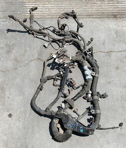
Detailed Toyota Yaris Engine and Associated Service Systems for Repairs and Overhaul 2005 Toyota Sienna MCL20 MCL23 MCL25 Series Repair Manual RM1163U 2002-2007 Toyota Avensis Chassis Wiring Diagram Engine Body Repair Manual. I have a 2004 Toyota Sienna.


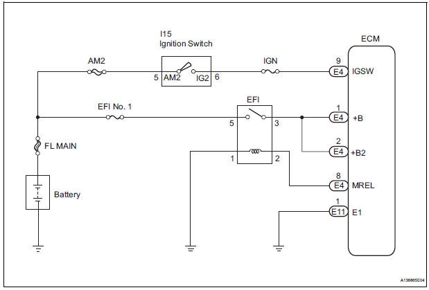
Toyota Sienna Service Manual Ecm Power Source Circuit Diagnostic Trouble Code Chart Sfi System 2gr Fe Engine Control System Engine

How to Fix 2004-2010 Toyota Sienna Sliding Door Will Not Open or Close With The Remote-How to Replace the Slide Door Lock Release Motor Assy.

04 sienna engine wiring. High School or GED. 2004 Toyota Sienna Electrical Wiring Diagrams. Please be sure to test all of your wires with a digital multimeter.

The coolant temp sender for the gauge has one wire dark green. Use DEI module 555F or 555U to bypass. 04 toyota sienna van wiring Home the12volts Install Bay Vehicle Wiring Information File Requests 04 toyota sienna van wiring Topic Closed Welcome Guest.

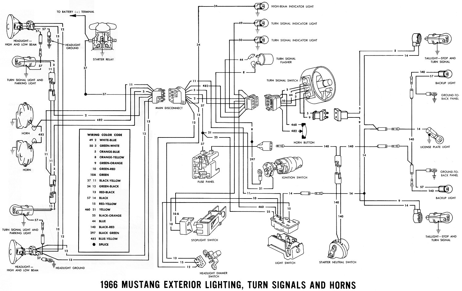
Toyota Hiace 2006 Electrical Wiring Diagram. It will help you understand connector configurations and locate and identify circuits relays and grounds. This high-quality Metra wiring harness is just what you need to replace your defective or aged factory wiring harness.

Schematic for Sienna 04 Cooling Fan circuit. All of this is pointing to the motor inside the door that essentially pulls the handle for you when you remotely open the door. The coolant temp sensor for the PCM has two wires and is located near the thermostat.

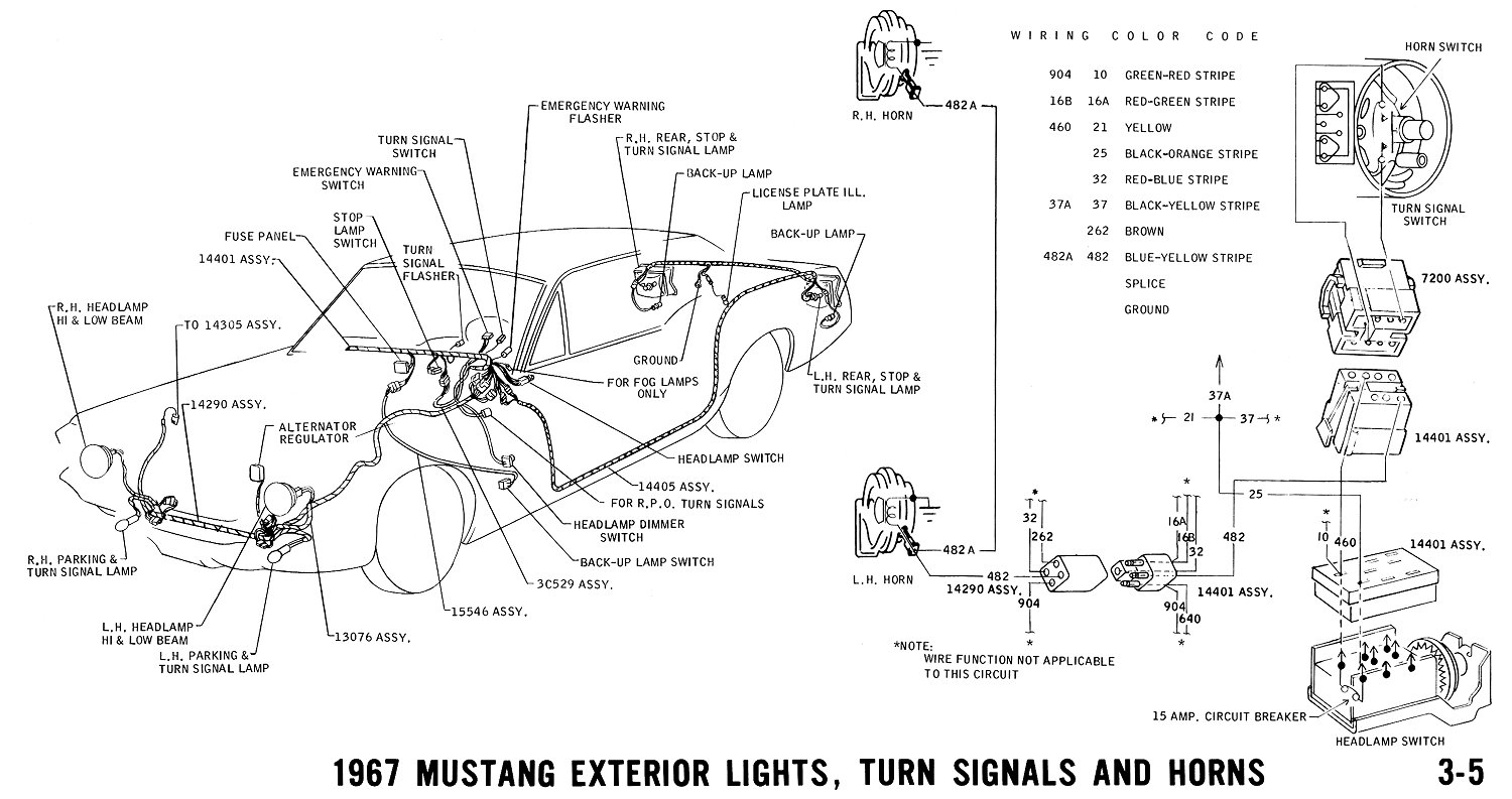
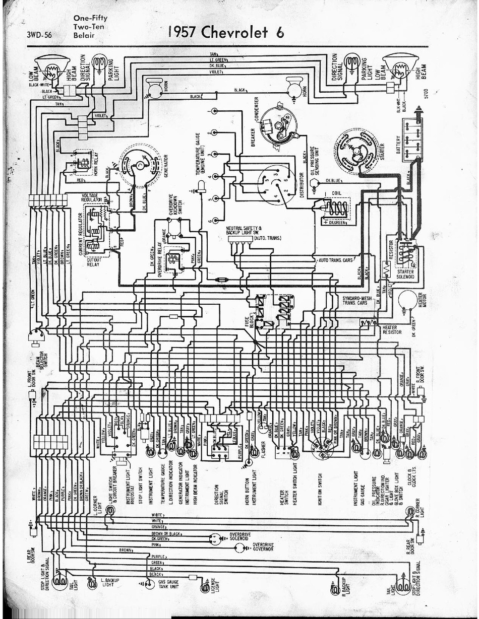
Draw in BLUE the Control circuit from the battery to ground of the Headlamp Circuit. We just bought a 2004 Toyota Sienna XLE Van 5 days ago and need to drive down from South Bend to Nashville TN 450 miles. Written for dealership mechanics this wiring diagram shows you how to follow the wiring from bumper-to-bumper.

Sienna repair manual downloadToyota 2004 Sienna maintenance manual04 sienna repair manual. Toyota Sienna 2004 Wiring Harness by Metra with OEM Radio and Speakers Plugs. Jump to Latest Follow 1 - 2 of 2 Posts.

Published by the Toyota Motor Corporation. That one is in the left cylinder head between the first two spark plus. Wiring diagram RENAULT Mégane III 15 DCi Diesel Engine K9K-837 year 2014.

Heres a video of me demonstrating the problem. 1 Remove the ETCS fuse from the engine room junction block. But now this is happening very frequently and I dont feelhear any engine knocking.

Last Post by Duraid1. In really good condition except it gets P0330 code 4-5 times a day I clear the code and it comes again. 1 they will test only by operating the key in the passenger door lock cylinder not the rocker switch on the door itself.

Toyota Hiace 1995-1999 Wiring Diagram. You could then just leave the inner door panel off and operate it that way or put the door panel back on. Compressorthe AC the front blower motor.

Listed below is the vehicle specific wiring diagram for your car alarm remote starter or keyless entry installation into your 2004-2007 Toyota Sienna. Took the van to a. Now when you turn on the AC the front blower motor stopped working.

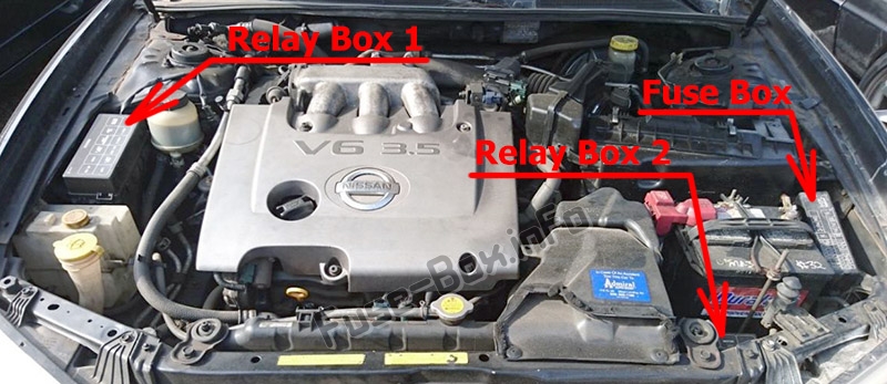
4 Reconnect the ECM connector. Fuse Layout Toyota Sienna 2004-2010 Cigar lighter power outlet fuses in the Toyota Sienna are the fuses 3 PWR OUTLET Power outlets 4 CIG Cigarette lighter and 21 AC INV. This task is described in Step 4.

Toyota HIACE service manual Free Download. Just be careful to retain the electrical connector for the power window if you leave the panel off so it doesnt get caught on something. 2 Disconnect the E4 ECM connector.

Technical Service Bulletins TSBs for the 2004 Sienna are official communications between Toyota their dealerships that describe processes for. This book includes color pages. Draw in RED the wires that supply B and Ground to the Integration Relay.

All Models Including Sienna CE Sienna LE Sienna XLE Sienna XLE Limited FWD AWD 33L 3MZ-FE V6 Engine. Assuming this is not a diesel engine. Home Tanpa Label 04 Sienna Engine Wiring - Sienna Ac Low Pressure 2000 Toyota Sequoia 2004 Repair - Weve tried putting rat poison stations under the car and taping rat poison inside the.

I have 2004 Toyota Sienna LE with 200K miles on it. 2 door lock ECU and theft ECU are in the center console. But this Saturday the check engine vehicle stability control and traction control lights turned on.

You will not find these wiring diagrams in the factory shop manual. The AC stopped working and we checked it out and replaced the compressor. Toyota Hiace 1995-1999 Repair Manual.

The DIS is a 1-cylinder ignition system in which each cylinder is ignited by one ignition coil and one spark plug is connected to the end of each secondary wiring. I would disconnect the wiring harness from the motor. 4 CHECK HARNESS AND CONNECTOR ETCS FUSE.

Its been happening for last 2 years onoff luckily I have been able to pass smog tests. Toyota Hiace 1989-2001 Service Manual. Recalling 8411 model year 2022 prius and prius prime vehiclesthe engine control unit ecu software may f.

3 Measure the resistance according to the values in the table below. 02-04-2020 0813 AM Prostar Wrote. Toyota - Camry - Wiring Diagram - 2001 - 2001 TOYOTA Wiring Diagrams PDF - Car PDF Manual Wiring.

High-voltage is generated in the secondary wiring and then applied directly to each spark plug. Covering Schematics Troubleshooting Relay Locations Routing Flow Charts System Circuits Ground Points Connector Part Numbers. Draw in GREEN the INPUTS which are used by the Integration Relay to control the lights.

One of the most time consuming tasks with installing an after market car stereo car radio satellite radio xm radio car speakers tweeters car subwoofer crossovers audio equalizer car amplifier mobile amp car amplifier mp3 player ipod or any car audio electronics is identifying the correct color car audio wires for your 2004 Toyota Sienna headlight bulb size you need for. This information outlines the wires location color and polarity to help you identify the proper connection spots in the vehicle. From what I can tell from researching the web the VSC and TC lights turn on as a result of the check engine light turning on.

TOYOTA 2006 Sienna Electrical Wiring Diagram EM01C0U TOYOTA 2007 4Runner Electrical Wiring Diagram. 3 located at one of the coils on top of the valve cover use the wire that is NOT BLACK white WHITE black or black 4 rear.

08 Equinox Stereo Wiring Diagram

08 Equinox Stereo Wiring Diagram

MITSUBISHI Car radio wiring diagrams. Premium Color Wiring Diagrams Get premium wiring diagrams that are available for your vehicle that are accessible Online right now Purchase Full Set of complete wiring diagrams so you can have full Online access to everything you need including premium wiring diagrams fuse and component locations repair information factory recall information and even TSBs Technical.


Looking For Wiring Diagram And Pin Outs For My Audio System Radio For My 2006 Equinox Has Onstar And Xm Ready Radio

Chevy Equinox Eps Wiring Diagram.

08 equinox stereo wiring diagram. Chevrolet S-10 1998 stereo wiring connector. Aveo Starter Replacement Wiring Diagrams. You can find the all the wiring diagrams for your 76 in the tech section under wiring diagrams in the search window and the whole radio pic here in the cab interior page.

Chevrolet Aveo Ecu Wiring Diagram. All wiring diagrams for pontiac g6 gxp 2008 model cars. Chevrolet S-10 1998 stereo wiring connector 3.

Chevy Equinox wire harnesses showcased on our digital shelves provide efficient worry-free operation of many parts of the vehicle. IF someone can help that would be GREaT. 2009 Chevy Aveo Wiring Diagram Fuse Box Download.

Cevrolet Aveo 2007 stereo wiring connector. 05-13-2008 0213 PM 6. I was wondering if someone has the stereo wiring diagram for an 08 subaru impreza.

Please verify all wire colors and diagrams before applying any information. Car Radio Switched 12v Wire. Ive checked the other radio wiring posts for my suv but the colors listed are not matching what I have.

I have a 2005 chevy equinox the low beam headlights went out high beams work just is it fuse. What do the colors on your wiring harness mean. Any user assumes the entire risk as to the accuracy and use of this information.

September 07 2015 at 12 35 am ip logged i am looking for wiring diagrams including lights horn and ignition for the 2015 chevrolet impala and equinox vehicles. Chevrolet S-10 1998 stereo wiring connector 4. Label it or splice to constant wire on aftermarket stereo first.

If you read it carefully it covers multiple levels of audio system packages and has all of the wire colors and details of the signal passing thru them. The radio harness does not provide a switched power source. Chevrolet Car Radio Stereo Audio Wiring Diagram Autoradio Connector Wire Installation Schematic Schema Esquema De Conexiones Anschlusskammern Konr.

Full explanation on our b. Radio Will Not Work We Have Hhr 2006 The Battery Went Dead And. How do you connect your wiring harness or interface to your stereo.

Chevy Aveo wiring diagram and fuse box diagram pertaining to Download. S2000 Stereo Wire Diagram Along with 2002 Chevy Impala Wiring. This Chevrolet Equinox Fuse Diagram GMC Terrain Fuse Diagram is 53 EPS F53UA Fuse 80A Power Steering Control Module LAF removal and installation instructions illustrations wiring diagrams component.

We carry Chevy Equinox wire harnesses that have a common style with black or white connectors on each end covered in certain areas by a special type of tape or sleeve as well as harnesses that have. Please help me figure this out. 2005 Chevy Aveo Radio Wiring Diagram Download.

AIR CONDITIONING Automatic AC Wiring Diagram 1 of 2 for Chevrolet Equinox LT 2013 Automatic AC Wiring Diagram 2 of 2 for Chevrolet Equinox LT 2013 Manual AC Wiring Diagram 1 of 2 for Chevrolet Equinox LT 2013 Manual AC Wiring Diagram 2 of 2 for Chevrolet Equinox LT 2013ANTI-LOCK All Wiring Diagrams for Chevrolet Equinox LT 2013 model. Run a wire to the fusebox for switched power. 800 x 600 px source.

Car radio constant 12v wire. The accessory turn-on and amplifier turn-on are controlled by the class 2 serial network. Read all of the instructions.

Whether your an expert Chevrolet Equinox mobile electronics installer Chevrolet Equinox fanatic or a novice Chevrolet Equinox enthusiast with a 2007 Chevrolet Equinox a car stereo wiring diagram can save yourself a lot of time. Also it makes installation a breeze. Im trying to install my new stereo but i cant figure out the wires.

2005 Chevrolet Equinox Stereo Wiring Not Matching - Im installing an after market stereo in my 2005 Chevy Equinox. The radio harness does not provide a switched power source. Check fuses if your unable to find 12 volts.

Electric Power Steering Installation Directions. 03082009 Fuel pump wiring diagram for 1998 chevy express. Chevy express wiring diagram.

Chevrolet radio stereo wiring diagrams. A car stereo wiring diagram can save yourself a lot of time. Radio Stereo Wire Harnesses for 2008 CHEVROLET EQUINOX wire harnesses for into car into factory radio wires amp bypass harnesses amp integration harness.

IMPORTANT - There are two 2 yellow two 2 gray and two 2 brown wires in this harness. Car Stereo Wiring Color Codes. For those of you looking to update and upgrade their audio systems in their 2012-2015 Equinox Terrain here is the OEM wiring diagram for the factory infotainment system and its components.

Chevrolet car radio stereo audio. Car radio switched 12v wire. MITSUBISHI Car Radio Stereo Audio Wiring Diagram Autoradio connector wire installation schematic schema esquema de conexiones stecker konektor connecteur cable shema car stereo harness wire speaker pinout connectors power how to install.

The picture below shows the wiring color codes for a CEA aftermarket radio harness that is included with most radios. Car radio wire diagram stereo wiring diagram gm radio wiring diagram. Car Radio Constant 12v Wire.

Automotive wiring in a 2007 Chevrolet Equinox vehicles are becoming increasing more difficult to identify due to the installation of. 2008 Chevrolet Equinox Car Stereo Radio Wiring Diagram. Chevrolet car radio stereo audio.

Locate the 12 volt constant wire first. Chevrolet S-10 1998 stereo wiring connector 2. Read all of the instructions.

Chevrolet Aveo Engine Harness Diagram Download. I dont want to destroy my old or new stereo wi. Engine Diagram Chevy Equinox Chevrolet Free Wiring You can try this website there is a lot of information on it concerning different chevy vans and products for online manual.

Brands like Pioneer Alpine Sony Kenwood JVC Boss and Jensen. Chevrolet Malibu 2002 stereo wiring connector. Listed below is the vehicle specific wiring diagram for your car alarm remote starter or keyless entry installation into your 2007-2011 Chevrolet EquinoxThis information outlines the wires location color and polarity to help you identify the proper connection spots in the vehicle.

Chevrolet Malibu 2002 stereo wiring connector 2. 2015 chevy equinox wiring diagram. All Wiring Diagrams For Chevrolet Hhr Ls 2007 Diagramas De Cableado Para Automóviles.

Today in our 2015 chevrolet equinox we ll be installing the curt t connector vehicle wiring harness with a 4 pole flat trailer connector part number 56094. Swapping yellow wires will cause damage to any aftermarket stereo.

1967 Mustang Wiring Diagram

Headlamps parking lamps fog lights horns headlamp stop turn signal and ignition switches taillights and backup. 1966 Mustang VIN and Data Plate Decoder Sheet.


1967 Mustang Wiring And Vacuum Diagrams Average Joe Restoration

Revised September 11 2013 Page II Table of Contents.

1967 mustang wiring diagram. The 1967 C o l o r i z e d Mustang Wiring and Vacuum Diagrams manual contains a complete and comprehensive collection of wiring diagrams schematics and electrical illustrations. Forel Publishing Company LLC 3999 Peregrine Ridge Ct. Wiring Diagram comes with a number of easy to follow Wiring Diagram Instructions.

Interconnecting wire routes may be shown approximately where particular receptacles or fixtures must be upon a common circuit. The Ford Mustang 1967. And white is connected to the F side The other two blkred and black are connect to alt and engine block.

When you employ your finger or even the actual circuit together with your eyes it may be easy to mistrace the circuit. However only the 67 and 68 diagrams have the supporting detail drawings. 10 1967 Mustang Engine Wiring Diagram Engine Diagram Wiringg Net In 2021 Mustang Engine Mustang Diagram 67 Mustang Engine Wiring Diagram And Mustang Wiring And Vacuum Diagrams Average Joe En 2021 12 72 Chevelle Engine Wiring Harness Diagram Engine Diagram Wiringg Net 1968 Mustang Diagram Mustang.

Print the wiring diagram off plus use highlighters to trace the signal. I have added 67-72 diagrams. 1968 Mustang VIN and Data Plate Decoder Sheet.

1 trick that We use is to print the same wiring diagram off twice. A wiring diagram is a kind of schematic which uses abstract pictorial signs to show all the affiliations of parts in a system. Collection of 1967 mustang alternator wiring diagram.

Alternator wiring diagram for 1967 mustang. These directions will be easy to grasp and use. Alternator regulator solenoid starter distributor plugs ammeter and starter neutral switch.

Ad Shop Quality Illustrated Mustang Repair Restoration Guides At CJ Pony Parts. 1 trick that We 2 to printing a similar wiring plan off twice. Hello looking for pics of 1967 instrument wiring pigtails.

1967 mustang wiper motor wiring diagram 67 mustang engine wiring diagram 1967 mustang engine wiring diagram. 1969 Mustang VIN and Data Plate Decoder Sheet. Anyway i attached a separate ground wire to my plain jane 1 wire 100 amp tuff stuff alternator 7068.

1967 Mustang Wiring And Vacuum Diagrams Average Joe Restoration 1967 Mustang Wiring Diagram. In my wiring diagram for a 67 ignition starting and charging systems there is only 1 brown wire. The attached photo may or may not help you.

1967 Wiring Diagrams Form FD-7795P-67 FD-7943-67 and How to Read Wiring Diagrams FD-7943-G. 1967 Mustang Wiring and Vacuum Diagrams. 2 Connect the Red White wire of the gauge harness to the SN74Z terminal marked 12 VOLTS.

The 1967 Colorized Mustang Wiring Diagrams is a complete and comprehensive collection of wiring diagrams schematics and electrical illustrations. 1968 ford mustang wiring harness schematic together with uo0x 15476 moreover ford ranger wiring diagrams further 69 mustang ignition wiring diagram as well. 68 Mustang Ignition Wiring Diagram Yamaha 40 Hp Wiring Diagram Wiring Library.

1967 Ford Mustang Wiring and Vacuum Diagrams Extracted from Form 7760-67 Form FD-7795P-67 FD-7943-67 FP-7635B and FD-7943-G ISBN. This includes revising the linetypes and colors to make them more readable both on screen and printed. Instrument cluster connections wiper switch headlamp switch ignition switch and lighter.

BTW you need to slow down when you take photos of your dash. Remove the standard grille and install a gt grille. WIRING THE BRAKE LIGHT INDICATOR.

Variety of 1967 mustang wiring diagram. 1967 Mustang VIN and Data Plate Decoder Sheet. 1967 Cougar Fairlane Falcon Mercury and Mustang Shop Manual Form 7760-67 March 1967.

1967 Mustang Wiring and Vacuum Diagrams. 1967 Mustang Wiring and Vacuum Diagrams - Average Joe. 1968 Mustang Wiring Diagrams and Vacuum Schematics.

When you make use of your finger or perhaps the actual circuit with your eyes it is easy to mistrace the circuit. 1967 Mustang Wiring and Vacuum Diagrams. Again the 1967 mustang diagram shows a split at the relay of the blkyel wire and connects some where on the alt.

1967 Mustang Wiring Diagram Manual - Free download as PDF File pdf Text File txt or read online for free. 1967 mustang wiring and vacuum diagrams average joe restoration size. Electrical 1991 mustang lx fuse block wiring diagram.

Ad Shop Quality Illustrated Mustang Repair Restoration Guides At CJ Pony Parts. Woodbridge VA 22192 Email address. Compiled from multiple Ford Motor Company publications this product contains information from.

Useful guide for car restorers fans and owners of one the greatest symbols in automotive industry. 1966 Mustang Wiring Diagrams. 1967 mustang wiring diagram 1967 Mustang Wiring And Vacuum Diagrams Average Joe Restoration Throughout 67 Diagram.

10 WIRING THE DASH LIGHTS. 1968 mustang starter solenoid wiring diagram. 1967 mustang wiring diagram.

If you have downloaded earlier versions of the 64-66 diagrams I have spent some time updating and correcting them. It is meant to aid all of the average consumer in developing a correct method. On a stock 67 dash the Speedometer is on the left and the Tach is on the right.

I have a 1967 Mustang and I need to connect a wire to the ignition switch where it is hot when it is in the ON and STARTCRANK position. There are 4 more wires that come out of the harness one thick black is conneected to the bat side of alt. It shows how the electrical wires are interconnected which enable it to also show where fixtures and components might be coupled to the system.

And white is connected to the F side The other two blkred and black are connect to alt and engine block. 10 1967 Mustang Gt Fog Light Wiring Diagram Pics. 85 mph is too fastgringreen I hope it zeros when powered up.

03 Maxima Radio Wiring Diagram

Nissan Vg30 Wiring Diagram 10 Nissan Nissan Maxima Automobile Industry. Nissan maxima radio wiring diagram 2015 nissan ud truck service manual monaquitaine com.


Nissan Colours Questions Answers With Pictures Fixya

Https Www Honeywellprocess Com Library Support Public Documents 34 St 25 19 Pdf.

03 maxima radio wiring diagram. Din Rail Wiring Diagram Wiring Diagram For Wire Rtd The Wiring. Bmw k1200lt radio wiring diagram 3. 03 Ford F150 Radio Wiring Diagram.

They only charge 10 to get the new one if you have an older copy. Latest Wiring Diagram For A 2006 Kenworth W900 2004 T800. Rasmussen An electrical wiring layout is a straightforward visual representation of the physical connections and also physical format of an electrical system or circuit Radio Stereo Wire Harnesses for 2001 NISSAN MAXIMA BOSE Pkg wire harnesses for into car into factory.

93 Nissan Altima Fuse Box Diagram Nissan Maxima Nissan Xterra Nissan Altima. 99 Nissan Maxima Bose Stereo Diagram - GentlmenWould anyone know where I can get my hands on the wiring diagram for a 99 Nissan Maxima Bose Stereo System. 1999 2000 2001 2002 2003.

Nissan Maxima Car Stereo Radio Wiring Diagram Radio Constant 12V Wire. Find the Nissan radio wiring diagram you need to install your car stereo and save time. The wiring is easily reached by removing the panel just to the front of the center console on the passenger side.

Smart Program Specific Metering Wiring Diagrams May Ppt Download. July 31 2004 at 903 PM IP Logged ooops. Knowing what every car radio wire does in your 2003 Nissan Maxima radio wire harness takes the guess work out of changing your car radio or fixing your car stereo.

Wiring Harness And Speaker Wire Diagram Nissan Frontier 2005 07 Crew Cab Nissan Altima Nissan Nissan Frontier. If you have a Nissan Maxima approximate years 2001 2002 2003 that looks like Figure 1 then you are likely to be suffering from the left channel of your CD player not working. Image result for drl wiring schematics 03 silverado.

Diagram 2012 Nissan Maxima Fuse Box Diagram Full Version Hd. Dbw To Dbc Conversion 03 Harnesses Wiring Diagram. Scroll down and find the Nissan wire guide you need.

Can also find the wire at the ECM. AF331 With images Commercial vehicle Nissan Line 1988 NISSAN SENTRA 2DR SEDAN wiring information. Fuse box diagrams location and assignment of electrical fuses and relays Nissan Maxima Maxima QX Cefiro A33B.

Smart Meter Electricity Meter Circuit Diagram Smart Grid Smart. Nissan Frontier Radio Wiring Diagram Nissan Frontier Nissan Sentra Car Stereo. The Maxima used a single DIN setup and the pocket which could be eliminated in favor of a double DIN stereo.

2006 honda crv radio wiring diagram bmw 3 series fuse box diagram 1997 lincoln town car radio wiring diagram 1997 lincoln town car stereo wiring diagram 2003 acura. Seventh Generation Maxima Stereo Wiring Diagram. Our 2003 Nissan Maxima radio wiring diagram shows you all the 2003 Nissan Maxima radio wire colors and what they do.

Manual transmission isuzu mbp6p. Having a Nissan stereo wiring diagram makes installing a car radio easy. 8 out of 5 stars 22 16.

2001 nissan maxima vacuum diagrams 2001 Nissan Maxima. 17 1996 Nissan Truck Radio Wiring Diagram Nissan Hardbody Nissan Pickup Truck Nissan Trucks. Nissan ud wiring diagram.

Nissan Radio Stereo Wiring Diagrams. 2000 nissan maxima bose amp wiring. 2000 Nissan Maxima Front Windshield Nissan Parts Deal.

Here is a list of radio wiring harness wire color codes and what they do. Diagram In Pictures Database 2000 Nissan Maxima Radio. DO NOT UNPLUG THE ECM.

Diagram 2003 Maxima Exhaust System Diagram Full Version Hd. Nissan Pathfinder 2001 2002 CD changer stereo wiring connector. Do not start the car with the cluster unplugged.

PinkBlue Radio Ignition Switched 12V Wire. Pluto ECU Intermediate 98 36-1 1-6Cyl Spark Ver 34F 16_03_2016HEX Pluto ECU Micro 4 Crank Signal Converter Ver 34C 01_10_2015HEX Pluto ECU Standard 2 Fuel Only Ver 34E 11_02_2016HEX. Diagram Radio Wiring Diagram For 03 Nissan Maxima Full.

16 Nissan Maxima Wiring Diagram Posted on January 23 2020 August 1 2020 by Roberta F. Nissan cars parts and spares for old nissans. Posted on Friday March 17 2006 - 2133 GMT.

7 The headlight relay is in the relay box under. Ford taurus questions 2003 taurus 8 alternators in 2. 1995 nissan altima engine diagram pdf download.

59 rows NISSAN Car Radio Stereo Audio Wiring Diagram Autoradio connector wire installation. 2006 350z bose full wiring diagram my350z com nissan and 370z forum discussion 03 2003 factory car stereo installation harness oem radio install wire stock help color code guide for audio autoradio connector schematic schema esquema de conexiones stecker konr connecteur cable shema visual system section av pdf. This is a common issue where you lose the sound on the left side speakers just when playing the CD.

6 Located on the rear of the instrument cluster in the 20 pin brown plug. Premium Color Wiring Diagrams Get premium wiring diagrams that are available for your vehicle that are accessible Online right now Purchase Full Set of complete wiring diagrams so you can have full Online access to everything you need including premium wiring diagrams fuse and component locations repair information factory recall information and even TSBs Technical. Here is a list of radio wiring harness wire color codes and what they do.

PinkBlue Radio Ignition Switched 12V Wire. I use 12 Volt Resource - they charge 20 for a CD that has wiring diagrams for every car or truck from like 1980 to 2006 and each year they release a new CD that covers all the new vehicles for that year. 1985 nissan 300zx car stereo wiring guide modifiedlife com.

I have given both with and WO Bose. 1992 maxima bose stereo had 16 wires nissan car radio audio wiring 2004 repair manual speaker help. To the steering wheel controls along with integrated double DIN navigation was an option from the factory00 01 OEM radio in a 02 03 - Maxima Forums7th Gen Nissan Maxima Bose.

1991 NISSAN 300ZX 2DR COUPE wiring information. Third Generation Maxima Stereo Wiring Diagram 1988-1994 The last generation of boxy Nissan Maxima the third generation Nissan sedan used the center console style reminiscent of the 240SX. Figure 1 - Nissan Maxima 2001 - 2003.

03 Ford F150 Radio Wiring Diagram. I have given both with and WO Bose. A wiring diagram is a kind of schematic which uses abstract pictorial symbols to show each of the interconnections of components in a syste.

Nissan Maxima Car Stereo Radio Wiring Diagram Radio Constant 12V Wire. We currently only have 1995 thru 2004 information available please check back later for further information Finding accurate and up.

110 Electric Plug Wiring

110 Electric Plug Wiring

15 Amp AC Power Inlet Port Charger Plug by Journeyman-Pro 110-125 Volt Socket Waterproof Electrical Outlet Receptacle 20-Inch Integrated Outdoor RVShore Extension Cord 5-15R 5278GCP1 48 out of 5 stars 1582. Print the wiring diagram off plus use highlighters to trace the signal.


110 220 Plug For Powerpro Shopsmith Forums

The red and black wires in 220v setups each carry 110v and the green wire is the ground.

110 electric plug wiring. With this wiring both the black and white wires are used to carry 120 volts each and the white wire is wrapped with electrical tape to label it hot. Step 2 - Attaching wire to the electrical receptacle. 110V 115V 120V 220V 230V 240V.

120V is the AC voltage on a single hot wire in your home with respect to neutral or ground. In this video well show you how to wire a removable grounded plug ends both the black and white. Wiring a 110V electrical outlet is a do-it-yourself task that can be completed by anyone with common tools.

In 110v plug wiring youre dealing with 14- or 12-gauge wire. Wiring a 110v electrical outlet is a do it yourself task that can be completed by anyone with common tools. By the way if youre wondering why the outlet you just bought has a label indicating its for a 115-volt plug or a 120-volt plug dont worry.

In 110v plug wiring you re dealing with 14 or 12 gauge wire. Install a 110-volt polarized electrical plug by connecting the white wire to the steel or chrome-plated screw the black wire to the brass screw and the bare ground wire if it is used to the green screw. More about how to wire 220volt outlets.

In this video I explain how a 110v site transformer works it probably doesnt work the way you think it does so this is good info. The key is to make sure you connect the wires to the proper terminals in the plug. If youre wiring a 3-prong plug you need 2-conductor cable with a ground.

A 110 volt outlet is the standard for usa electrical house wiring. It lacks a grounding contact and the plug slots are both the same size. According to previous the traces in a 110V Plug Wiring Diagram signifies wires.

These plug ends have a 2 part construction the housing a. Wiring diagram for dual outlets. 1 trick that We 2 to printing a similar wiring plan off twice.

Wiring schematic for making connection. For a standard 120 Volt outlet. The black wire is hot the.

This can be confusing but the bottom line is they are referring to the exact same thing. The most common electrical plugs and plug connectors are 15 20 and 30 amps. Wiring a 110v electrical outlet is a do it yourself task that can be completed by anyone with common tools.

Larry campbell is an electrical contractor with 36 years of experience in residential and light commercial electrical wiring. How to wire plug outlets for 110v electricity what youll need. 110 volt - Electrical Plugs Connectors - Wiring Devices Light Controls - The Home Depot.

Nearly every home in America has 110v electricity pulsing through its outlets and fixtures to power the home. Answer 1 of 11. This ensures that the plug and the box are now grounded.

This circuit doesnt make use of a neutral wire and the ground wire is connected to the ground terminal on the device. The amperage of an electrical plug has a direct influence on the wattage or the measurement of electrical power. The hot wire goes on the brass terminal screw the white wire goes on the chrome one and the ground wire goes.

The hot wire goes on the brass terminal screw the white wire goes on the chrome one and the ground wire goes on the green one. The narrow blade is hot The wide blade is neutral The circular hole is ground FYI. The first this to do is attach the bare wire to the back of the electrical box wrap around one of the screws but leave enough of a tail to attach the the green or blackish screw at the bottom of the plug.

Its a source that provides 110 volts ac 5060hz from the city power lines. But it does not mean connection between the cables. The neutral wire from the circuit is shared by both sets.

110 Volt Plug Wiring Diagram. With four-wire setups there is a white wire which is called the neutral or common wire. Injunction of 2 wires is usually indicated by black dot at the junction of two lines.

Ensure that your new plug or connector has the. 110 electrical outlet wiring diagram. In order for that system to work the electricity must run from the main circuit panel to every room of the house.

It detects probable improper wiring conditions in standard 110-125 VAC outlets Provides 6 probable wiring conditions that are quick and easy to read for ultimate efficiency Lights indicate if wiring is correct and indicator light chart is included Tests standard 3-wire outlets UL Listed Light indicates if wiring is incorrect Very handy and easy to use. Sometimes the cables will cross. If installing a plug on an appliance where the wiring is not color coded observe the connection before cutting the old plug from the appliance.

Modern homes all have 3-plug outlets that are comprised of a. Residential electrical devices all use a standard color code for wires and terminals and if you follow it its almost impossible to wire a 110V outlet incorrectly. Power voltage x current with current measured in amps.

The hot side of the outlet the side that can deliver a shock is wired to the threaded socket if the wires are reversed. Hot neutral and ground. With 220v wiring both three and four-wire setups are possible.

A typical 110v wiring schematic requires three different wires. Youll often hear voltages in your home referred to as 110V 115V or 120V. The wide prong on the plug links the threaded base of light bulbs to the neutral terminal the wider slot in the receptacle.

A ul knot secures the cord. When you make use of your finger or perhaps the actual circuit with your eyes it is easy to mistrace the circuit. In 110v plug wiring youre dealing with 14 or 12 gauge wire.

The slots are configured to accept only plugs from compatible appliances.

Jumat, 18 Maret 2022

1970 Mustang Engine Wiring Diagram

Factory Alarm Disarm Wire -. As well as the 302 and 429 Boss engines which have helped make the Ford power teams synonymous with performance and winning.


Vintage Mustang Wiring Diagrams

Wiring - except GT 350 500.

1970 mustang engine wiring diagram. Or some of you might want to do a full replacement of all of your 1970 Mustangs wiring to ensure your electrical system is up-to-date and reliable. Regular 1995 Now On Sale for 1495. Brake Light Positive Wire.

Colorized 1970 Mustang Wiring Diagrams and Vacuum Diagrams pdf download includes 483 pages. The mustang gt also disappeared for the 1970 model year. Light Green Brake Light Positive Wire Location.

Additional 1970 Mustang Reference Book Downloads You May Find Helpful. 1970 Mustang Part and Body Illustrations. Wiring diagram wiper motor Ford Thunderbird 1995.

Mach 1 Club Mustang Mach 1 Garage Electrical Wiring 1970 mustang wiring diagram. Engine PerformanceThe 1970 engine lineup avail- able in Mustang is unequalled. The 1970 C o l o r i z e d Mustang Wiring Diagrams manual contains a complete and comprehensive collection of wiring diagrams schematics and electrical illustrations.

Use them with all due caution. 01-07-2011 1108 PM. After visiting our store mustang lovers find we also have the best selection of mustang parts great prices and top notch service.

Horn Negative Wire Location. Any Wire With A Tan Stripe Or A Yellow Stripe Tachometer Wire Negative Wire Location. Ad Shop Quality Ford Mustang Wiring Diagram At CJ Pony Parts.

Ford mustang enthusiasts come to us looking to buy top quality mustang part online. To finish the installation you would typically just reconnect the plug to the wiring harness into the voltage regulator. Vintage mustang wiring diagrams.

Mach 1 club mustang mach 1 garage electrical wiring 1970 mustang wiring diagram. Each diagram and illustration is from an original Ford Motor Company publication and are the same manuals used by Ford technicians to troubleshoot electrical repairs. Administrator Mustang 428 Cobra Jet Registry Owner Muscle Car Research LLC.

70 Mustang Parts Illustrations and Body Part Illustrations Book Download includes 272 pages. Neutral Safety Switch FMX 1970 Mustang Wiring Connections. Tachometer Wire Negative Wire -.

The 1970 Colorized Ford Mustang Wiring Diagrams pdf download e book contains a complete and in depth collection of wiring diagrams schematics and electrical illustrations as well as vacuum hose installation and routing. 1970 mustang wiring diagram. Instrument Cluster and Related Parts.

Air Cleaner - 8 cylinder - Ram Air. However I am building a new wiring harness for my car so I purchased a new Mustang Voltage Regulator Plug and connected the ends using my own wiring diagram. 1970 mustang ignition switch wiring diagram.

It includes an all-new 351-cid. 1970 Ford Mustang Colorized Wiring Diagrams Usb. Jump to Latest Follow 1 - 20 of 21 Posts.

Regular 1995 Now On Sale for 1495. Chassis wiring from headlights to taillights and all in between. Builds modifications reviews engine swaps classifieds troubleshooting maintenance and more.

At Steering Column Harness. 1970 Colorized Mustang Wiring Diagrams Fordmanuals Com. If the same as on a 93 the wiper motor has two connectors.

These all-out engines are backed by the rest of the Mustang lineup designed to. 1970 Mustang Exterior Lights Turn Signals Page 2 How To S 69stang Com And 1969stang The 1969 Supersite. With a wiring harness you can make sure your engine lights and gauges are all up and running with one convenient kit.

Courtesy Instrument Door Dome Map Glove Box C Pillar Ignition Key Warning Buzzer Clock Feed Luggage Compartment Lamp Headlamp on Reminder Buzzer Cigar Lighter. Terminal and harness assignments for individual connectors will vary depending on vehicle equipment level model and market. Wiper switch to motor park and return - red wiper switch to motor park return - black.

1970 mustang wiring diagram. 2005-2010 Mustang Talk 2011-2014 Mustang Talk 50L Tech Classic Tech 2005-2010 Mustang. Colorized 1970 Ford Mustang Wiring Diagrams and Vacuum Diagrams download Includes 483 pages Description.

The grouping of diagrams by section is similar to how the Ford Motor. Wiper switch to motor high - dark brown orange wiper switch to motor low - white ground - black Connector B park switch. The portion of the wiring diagram that has to do with the voltage regulator is shown below and.

1969 mustang instrument cluster wiring diagram wiring diagram is a simplified within acceptable limits pictorial representation of an electrical circuit it shows the components of the circuit as simplified shapes and the capability and signal contacts. 1970 Mustang Exterior Lights Turn Signals Page 2 How To S 69stang Com And 1969stang The 1969 Supersite. Ad Shop Quality Ford Mustang Wiring Diagram At CJ Pony Parts.

One is the ignition wire from the tachignition switch junction the other is between the circuit board and another key powered junction that also leads to the ignition switch refer to my schematic. 1970 mustang ignition wiring diagram diagrams demo colorized exterior lights turn and vacuum cd rom ford vintage 1964 average marker rear light issue. There are also at least two special resistance value wires actually 3 incorporated into the main harness for the 70 Stang.

Mustang Wiring Diagrams 1970 Mustang Exterior Lights Turn Signals Page 2 How To S 69stang Com And 1969stang The 1969 Supersite 1970. 1970 mustang wiring diagram. Costs something like 15 from the usual vendors.

At Switch Above Brake Pedal.

1970 Cadillac 472 Engine Diagram

1970 Cadillac 472 Engine Diagram - Quadrajet Vacuum Port Rochester Quadrajet Carburetor - Norman Blog Senin 01 November 2021 The 425 472 and 500 cadillac engines of the late 1960s and 70s. Home Specs Cadillac 1970s General Specs.


I Own A 1970 Cadillac Deville With A 472 Engine Some 472 Have Two Belts In Tandem Going From The Crank To The Ac

Story By Benjamin Hunting.

1970 cadillac 472 engine diagram. Cad company specializes in 472500 and 425 engines providing custom cadillac engine building parts information and accessories for cadillac 500 472. When Cadillac debuted its new creation in the 1968 models the V-8 was produced with a 430-inch bore and 406-inch stroke to yield 472 cubic inches 77 liters the largest passenger car engine in the industry. Will work with or without a superheat switch.

1970 coup deville w 472. 1970 coupe deville 472 stock. Drag on your engine resulting in better fuel economy.

I also need to know where the transmission gets its vacuum supply from for. Unit price per. Piston Dis place ment Cubic Inches.

Cadillac 1970s General. Joined Aug 24 2008. 472 Cadillac Engine Wiring Diagram Ditulis samlicek Rabu 31 Maret 2021 Tulis Komentar Edit.

1970 Cadillac comprehensive vacuum diagram not for 75 series not for 69. Right now this 111517212933455675. Point Gap adj in to misfire then out.

The firing order is 1-5-6-3-4-2-7-8. The 1970 cadillac has a 472 engine and a rochester 4 bbl carb. I need to know where the vacuum lines go to from all the ports on the carb.

1486238 was block casting number 68-69. Although for much of its early life Cadillac was known for building high performance cars capable of going head-to-head with the worlds best by the end of the 1960s the brand had shifted into the late stage land yacht phase of its existence that guided it for much. This guide is mostly unchanged in nearly 20 years aside from a few minor details but is still a popular starting point for people planning a build.

Vehicles with Similar Dimensions. Shop 472 Cadillac V8 Engine parts and get Free Shipping on orders over 99 at Speedway Motors the Racing and Rodding Specialists. Complete basic car included engine bay interior and exterior lights under dash harness starter and ignition circuits instrumentation.

I own a 1970 cadillac deville with a 472 engine. Read Or Download The Diagram Pictures Cadillac For FREE Engine Diagram at CROWDFUNDING-DONATEDEMOAGRIYACOM. We specialize in 472 500 and 425 motor parts custom cadillac engine building parts information and accessories for cadillac 500 472 and 425 engines.

Diagram firing order for a 1987 cadillac deville 41 engine. October 22 2014 082333 PM. 472 Cadillac V8 Engine parts in-stock with same-day shipping.

The term Cadillac V8 may refer to any of a number of V8 engines produced by the Cadillac Division of General Motors since it pioneered the first such mass-produced engine in 1914. Block casting number is on the top leftish side of the flange where it butts to the transmission. Most commonly such a reference is to one of the manufacturers most successful best known or longest-lived 90 V8 engine series.

Find cadillac 77l472 starters and get free shipping on orders over 99. Home Tanpa Label 1970 Cadillac 472 Engine Diagram Solved What Is The Firing Order On 70 Deville 472 Engine Fixya. Northern auto parts kits come.

Access our GM Cadillac 1967-1989 Firing Orders Repair Guide by creating an account or signing. When Cadillac debuted its new creation in the 1968 models the V-8 was produced with a 430-inch bore and 406-inch stroke to yield 472 cubic inches 77 liters the. Plus also the snorkel damper is not there on the 69.

There are 2 vacuum ports on the back of this carb. These include the pioneering overhead valve 331 cu in 54. 1949 - 1970 Cadillac New Parts Catalog Your Classic Car Experts New Parts Reproduction New Parts Replacement RebuiltRefurbished Parts Used Parts.

According to my Chilton book this is same for either engine. 11 X 17. Engine ferrari 288 gto cad engine flathead straight 8 cad engine ford 2.

1969 1970 Cadillac Color Wiring Diagram. Reply 4 on. I could really use a copy of the vacuum diagram.

1970 Cadillac 472 Engine Diagram - Cadillac S First Front Wheel Drive Production Car The 1967 Hemmings Motor News. Jul 18 2014 1970 cadillac deville. 9 Aug 25 2008.

With 1051 compression it produced 375hp and 525-lbs ft of torque when it was introduced. The 1970 Cadillac DeVille Series measures 7980 inches in width The 1970 Cadillac DeVille Series measures 22500 inches in length and has a wheelbase of 12950 inches. Total Car Production.

Going into my 1978 Cadillac Coupe Deville replacing. The Cadillac 500ci V8 Was GMs Last Classic Big Block. Now I cant find my copy of the service manual go figure.

1609110 was 77-79 425. I have a 1970 cadillac deville with a 472 enginei have. 472 cadillac v8 parts 472 500 steel chrome material type.

The lowest price kits out there with brand name components. GM Cadillac 429 V8. Shipping calculated at checkout.

The lowest price kits out there with brand name components. Discussion starter 1 aug 2 2014 edited. Recent rebuild but when the car got moved during the rebuild all the tags we had labeled got wet and disappeared.

For 1970 Cadillac increased the stroke. General 68-85 472500425368 Cadillac Engine Tech. I need the wiring oder for spark plugs for a 1970 cadellac deville a diagram of my distributor would help.

Cad Company CTA250 cam stage 1 rocker shaft push rods and valve springs assembly HEI. Bottom of the 1968 cadillac engine with the oil pan removed. 454 bore and stroke chart Lit plug immersionfreeze plug part number with lit cord Mar 23 2016 therefore what i need to know is the following.

Ignition Timing BTDC or Mark. About where the distributor would be on a Chevy. GM Cadillac 368 425 472 500 V8.

B sedan deville hardtop. The air pump I bound to have a bad rubber bladder and that vacuum line should be blocked. Standing at the front of the car looking at the engine 1 piston is at 9 oclock on the distributor and it turns clockwise.

Vi arbetar bara med nya och renoverade delar till cadillac. A guide to narrowing down what kind of engine build is right for you based on usage power output etc. Gallon of Gas.

The 69 will be similar except there is an air pump and no trans solenoid. Instructions for installing the cadillac 472500425 engine in a modern car or truck some 60s and most. 500 has roughly a 43 stoke 472 roughly 40 so you are looking for around a 14 difference.

Cadillac car parts for sale 1950 s to 2000 s 0 1969 1970 cadillac.

1966 Ford Falcon Wiring Diagram

Was 1217 107mph. I am installing a Painless kit and just need the diagram for the headlight switch and windshield wiper switch so i can get the dash finished up.


Ford Falcon Maverick And Pinto Wiring Diagram Fully Laminated Poste Kwik Wire Electrify Your Ride

We are always adding other years makes and models to our inventory and currently carry close to a.

1966 ford falcon wiring diagram. Ford Ranchero Ford Falcon Ford Fairlane Ford Torino Mercury Comet and Mercury Montego Parts Online. 1486 x 1024 312K CLICK HERE TO VIEW IN HIGHER RESOLUTION 2638 X 1818 - 768KAlternator Motorcraft 38 42 55 60 61 AMP - Printed Circuit 1965-1972. 1965 Mustang Wiring Diagrams Average Joe Restoration Mustang Engine 1965 Mustang Classic Mustang.

1966 ford falcon blew up the 351 so its time for a 418 clevor. Here we have Ford Wiring Diagrams and related pages. 1964 Ford Falcon Wiring Diagram Wiring Diagrams Of 1964 Ford 6 And V8 Falcon All Models Part 2 1964 Ford Falcon Well Pump Pressure Switch Well Pump.

7 99 3 69 shipping. Ford ba wiring. Ford Fg Ute Wiring Diagram Diy Wiring Diagrams U2022 Rh Socialadder Co Fg Falcon Ute Wiring Diagram Electrical Wiring Diagram Wiring Diagram Circuit Diagram.

Now let us take you to see this wiring diagrams of the 1965 ford 6 and v8 fairlane part 1. 1966 Ford Falcon blew up the 351 so its time for a 418 Clevor. The Painless wire harness is designed to be used in 1965 1966 Ford Mustangs.

This circuit and wiring diagram. 11 X 17 18 X 24 Add to Cart Complete basic. Ford falcon 1962 ignition distributor cap by wve.

1965 ford wiring diagram. Schematics for 1966-1972 Falcons here. 1966 n light ford oil press.

Same as above just Black White. Complete wiring diagram for a 1966 Falcon Figure 1 Figure 23 Figure 45 Figure 6 Figure 6b Figure 7. Iiiiii signals and e for model 71 only.

Hi my name is Anthony I was hoping that I could get from you the wiring diagram for a 2003 Ford ranger FX1 the diagrams that I am looking for are the connectors for the multi function switch connectors c202a and c202b what happened is I pulled the connectors off to change the MGS because my turn signals where not working and both the. 1964 Wiring Diagrams. 1965 ford truck wiring diagramsWhen creating the colorized wiring diagrams for the 1965 and 1966 model years i compared the two to note any differences between them.

7635B May 1975 1966 Falcon Comet Fairlane and Mustang Shop Manual Form 7760-66 August 1965 and 1966 Wiring Diagrams Form FD-7795P-66 and How to Read Wiring Diagrams FD-7943-G. 1966 ford falcon wiring diagrams schematics. Anthony January 28 2022.

1962 ford truck wiring diagrams. If anyone has a copy of a wiring schematic or a wiring diagram or both I would greatly appreciate it. 1965 ford galaxie color.

Wiring System 8 Cylinder Engine - Typical 1965-1972 F100F350. To i need see a wireing of wiper motor switch for hardtop ignition help www carmodder view topic icc radio mods hacking 1966 all makes models parts l151 cm service 24 volt system 966c wheel loader avspare fan. 6 breaker regulator distributor fairlane 3wd- high 43 dirtion parking light parking light gnal high beam beam 6629.

1962 Chevy Truck Wiring Diagram In 2021 Chevy Trucks Diagram Chevy. Parts car wiring harness from junkyard or falcon vendors like the following. How To Wire My Car - 101.

1966 Ford Falcon Color Wiring Diagram. Falcon Diagrams Ford Diagrams Chevy Diagrams Chrysler Diagrams Other Diagrams. Though its easy enough to do it would be a hell of a lot easier with a diagram.

1966 ford fairlane wiring diagram manual. Unit price per. Ford EFI injector wiring conversion Bank firing to Independently fired - Figure A 1990 50 HO EFI Mustang Wiring - Drawing A Ford 74 IDI.

94 out of 100 based on 108 user ratings the wiring diagrams of 1965 ford 6 and v8 fairlane part 1 can be download for free. You have a couple of options. For fuse specifications and wire color designations see the Wire Index.

All diagrams include the complete basic car interior and exterior lights engine bay starter ignition and charging systems gauges under dash harness rear clip etc. 1966 Mustang Wiring Diagrams Diagram Mustang Mustang 1966. 1966 wiring diagram.

1966 Falcon Wiring Diagram Manual. Voltage Regulator Ford 15 Volt - Negative Ground - Alternator. Oil light flickers on my 61 ford.

Home 1961 1962 ford falcon color wiring diagram. 1682 x 1024 250K. Painless wiring 14 circuit wiring harness ford falcon mustang 1966-76 pw10123 Designed for 1966 - 1976 Ford muscle cars including Galaxie LTD Falcon Fairlane Mustang Maverick Torino and Ranchero this 14-circuit universal harness features Ford OEM colour codes and our unique covered micro-fuse block.

All wire is 600 volt 125 c TXL. In the following pages you will be able to find some great tips and examples on how to do some of the wiring projects you may have been afraid to tackle. Falcon diagrams 64 ford wiring diagram mustang comet automobiles color laminated 1960 1969 63 motors other car.

Buy now for the best electrical repair infothe factory wiring diagram. - Figure A as a GIF file - Figure A as a PDF file. MACs Antique Auto Parts.

Exterior Light Turn Signals And Horns Wiring Diagrams Of 1966 Ford Throughout 1967 Fairlane Diagram Diagram Mustang Mustang 1966. Quick view choose options. Falcon diagrams ford color laminated wiring 64 hardtop ignition switch help 1964 ranchero l151 cm 1966 muscle cars 57 65 63 diagram automobiles no reading on gas gauge mustang alternator wiper motor to for 1965 average dash instrument testing original book colorized 1963 horn i have a 67 fairlane when press the circuit w truck.

If i was going to replace the wiring loom in a 67 falcon i could use anything from 66-85. All diagrams use factory colors including tracers when applicable. Diagram is laminated in plastic for years of use.

Shipping calculated at checkout. Falcon 1966 fairlane turn signals and exterior lighting horns. Standard automotive wire is GPT 300 volt 80 c with PVC insulation.

This complete automobile wiring system has been designed with four major groups. Ford Falcon - Maverick Pinto 1960 - 1973 1960 through 1963 Diagrams also cover Mercury Comet. Early model falcon wiring diagram in COLOR all on one sheet.

Here you will find Wiring Diagrams related to the Ford Falcon. The picture is an example of a wiring diagram but is not the exact diagram for this vehicle. I am trying to find a wiring diagram for my 66 Falcon and not having much luck.

Wiring diagrams and descriptions of the various circuits seem to be a rare thing for Ford manuals - out of the 4 or 5 manuals I own for this era Ford vehicles only one - the 1964 Comet and Falcon Shop Manual - has some decent wiring diagrams and descriptions and even they have some odd head-scratching errors on them. Pillar courtesy light instrument light.

03 Nissan Maxima Engine Diagram

03 Nissan Maxima Engine Diagram

Community Member Credit. Nissan ud wiring diagram.


Fuse Box Diagram Nissan Maxima A33 1999 2003

Intake Manifold Hose Diagrams.

03 nissan maxima engine diagram. Posted by s018700 on Nov 25 2009. Access our Nissan 350Z Maxima 1999-06 Intake Manifold Repair Guide Removal and Installation by creating an account or signing into your AutoZone Rewards account. We currently only have 1995 thru 2004 information available please check back later for further information Finding accurate and up.

Post by Memo240. More specifically a thermostat housing. Fuse Box Diagram Nissan Maxima and Maxima QX A33.

1993 Nissan Maxima engine diagram. Fuse box diagram fuse layout location and assignment of fuses Nissan Maxima and Maxima QX A33 1999 2000 2001 2002 2003. Posted on Jul 03 2012.

CA18DE CA18DET Forum. Discussion Starter 1 Aug 6 2015. Add your vehicle in Manage My Vehicles.

Pins 108 Pin 110 This is the Rear O2. An expert that got 10 achievements. Im not sure if i put it in the top or bottom hose.

I looked on eBay and found a replacement for 20 bucks vs 80 for OEM. Drive Belts Replacement Procedure 2000-2003 Nissan Maxima Drive Belts Replacement Procedure. Changing the spark plugs on a 2002-2003 Maxima is not something you should have to do until around 100000 miles.

The reason is that in order to replace the 3 plugs in the rear cylinder. Thermostat in my 1989 nissan maxima. Car Maintenance 10 Things Every Car Owner Should Know - The Short List.

Once you sign in follow these instructions to access our Repair Guides. Here is the diagram. Mtd 13a2606g190 Lt 1500 2003 Parts Diagram For Engine List 3.

Intake manifold collector torque sequence-25L engine. Very helpful when it comes to diagnosing P030x CEL Codes. Parts fit for the following vehicle options.

The Nissan Maxima utilizes a crankshaft position sensor in order to regulate the engine timing. 2000 Nissan Maxima Front Windshield Nissan Parts Deal. If you have a CEL for random misfire below the common codes.

Replacement of the plugs is something that Nissan recommends you see your dealer to do. Diagram 2005 Nissan Maxima O2 Sensor Wiring Diagram Full. Fuse box diagrams location and assignment of electrical fuses and relays Nissan Maxima Maxima QX Cefiro A33B.

Im interested in finding detailed wiring diagrams for all the functions of a power seat for my 2006 Nissan Altima 25S. The mount was fully busted. Technical Engine Tuning Nissan Tires Wheels Brakes and.

Reference photo of the VQ35DE Engine Firing Order for the Nissan Maxima. Manual transmission isuzu mbp6p. Nissan Truck Classifieds Nissan Titan Forum Nissan Pathfinder Forum Infiniti QX4 Forum Infiniti QX30 Forum Infiniti EX35 EX37 and QX50 QX55 Forum Infiniti JX35 QX60 Forum Infiniti FX35 FX45 FX37 FX50 QX70 Forum Armada Forum QX56 Forum QX80 Forum Nissan NV200 Forum.

Upon inspecting the two mounts they were pretty much the same. If you ever need to go two layers up or down ie. I Have A 2000 Nissan Maxima 3 0l It Has A Check Engine Light.

1990 Nissan 240sx ca18det swap. 2003 2020 Nissan Murano Timing Marks Diagram 3 5 L Vq35de Engine. I need pin outs of connectors and color of wires for all connectorssmile.

1991 NISSAN 300ZX 2DR COUPE wiring information. Maybe add this to the FAQ if one of you more knowledgeable guys run through it and see if this guys diagrams check out. Access our free Vacuum Diagrams Repair Guide for Nissan Maxima 1993-1998 through AutoZone Rewards.

Fully loosen each belt. See Note 251 - Nissan Starter Wires Diagram. VG30E vacuum hose diagram.

The stock plugs are platinum tipped and should last a very long time. This Vehicle Is Equipped With Two Start Wires. Helped me out with learning which gold canister is the FPR I.

Fits Maxima 2004 - 2007 10 people have looked at this part recently. AF331 With images Commercial vehicle Nissan Line 1988 NISSAN SENTRA 2DR SEDAN wiring information. LE Premium S SR SV Sport.

Diagram Radio Wiring Diagram For 03 Nissan Maxima Full. When the Maximas ECM determines that there is an issue with the signal coming from this sensor itll throw the P0335 trouble code. Engine Transmission.

1999 2000 2001 2002 2003. I need to find a diagram but am having trouble locating one. Nissan Maxima VQ35DE Cylinder Firing Order Cylinder Numbers.

DO NOT START ENGINE WITH INSTRUMENT CLUSTER UPLUGGED. 0002 of 0930 Volume 0. See Installation Note 144 - Bypassing Transponder Theft System.

As a general rule of thumb it is typically easier to accommodate an older ECU into a newer engine then the other way around. 1999 2000 2001 2002 2003. Engine Transmission Mounting are shipped directly from authorized Nissan dealers and backed by the manufacturers warranty.

Click image to see it larger. A vacuum hose schematic for your vehicle can usually be found under the hood. Both Must Be Powered In Order For Vehicle To Start When Engine Is Cold.

I decided to finally replace the upper torque mount on my 2009 7thgen Nissan Maxima with 220K miles. This sensor uses a reluctor to gauge the position of the crank. 2003 Grasshopper 325 Mower Engine Assembly Parts Diagrams The Here is a picture gallery about 1997 nissan altima engine diagram complete with the description of the image please find the image you need.

02142021 1008 am. 94 ECU 96 then carefully read the previous post related to the 95 ECU. Suspension Components For 2000 Nissan Maxima Courtesy Parts.

Listed below is the vehicle specific wiring diagram for your car alarm remote starter or keyless entry installation into your 2002-2003 Nissan MaximaThis information outlines the wires location color and polarity to help you identify the proper connection spots in the vehicle. I need an engine schematic for a 03 nissan maxima.

Kamis, 17 Maret 2022

toro lx 460 manual

When the welder revs up to weld mode oil. 4 1 5 421 Tipo de carrocería.


Toro Lx460 Lawn Tractor Specs And Service Data Wersis Net

Toro LX-460 Lawn Tractor wKohler Engine Ex Cond Needs Drive Belt 400 WILMINGTON south chicagoland pic hide this posting restore restore this posting.

. Favorite this post Mar 9 CERTIFIED ORGANIC AND COMMERCIAL HAY FOR SALE 0. View More Carbpro Carburetor for Cummins Onan P220V P248V P220G 20Hp Engine B48G B48M LX790 Nikki 6100 27 281 146-0496 146-0699 146-0661 Toro LX-460 Mower Carburetor CARBURETOR EMISSIONS PERFORMER 16-18 HP. Branca Manual R 48900.

2012 Joined Feb 9 2015 670 Posts. MONTANA LS 14 ECONOFLEX 8V 2P 2018. Favorite this post Mar 9 ROUND BALER TWINE FOR SALE 0 south chicagoland pic hide this posting restore restore this posting.

Branca Automático R Consulte. Es financiable 62 Tiendas oficiales. Preto Automático R 131460.

Branca Manual R Consulte. It keeps burning out the ignition module. MOBI 10 8V EVO WAY 2018.

Lowering Springs Jeep Commander 441. Eléctrica 404 Asistida 2 Hidráulica 1 Otras características. Oferta de Autos e peças em Sergipe Sergipe.

SUV 410 Hatchback 3 Monovolumen 1 Color. Solo tiendas oficiales 15 Dirección. Jun 11 2014 06 Vette LS2 440 CI Auto 500 RWHP Fast 102 big cam ported heads - Cold Idle If this is your first visit be sure to check out the FAQ by.

Na OLX você encontra as melhores ofertas perto de você. TRACKER 10 TURBO FLEX LTZ AUTOMÁTICO 2022. HILUX 27 SRV 4X2 CD 16V 2015.

Branco Manual R 48900. SAVEIRO ROBUST 16 8V. Works like a charm for my old cub 1912 with a 19.

Gris 107 Blanco 71 Rojo 26 Plateado 24 Negro 20 Azul 6 Marrón 4 Gris oscuro 1 Violeta 1 Ver todos. FAZER YS 250 2006. As with all our Toro Genuine Parts Toro belts are designed and manufactured to fit a specific application for a piece of Toro equipment.

08 535i Engine Diagram

Made to keep your vehicles engine running cool Designed to maintain proper cooling level and prevent overheating. 5 out of 5 stars.


Bmw E60 5 Series Turbocharger Replacement N54 Engine Pelican Parts Technical Article

český deutsch ελληνικά english US english español Français italiano 日本語 한국어 Nederlands polski português русский svensk ภาษาไทย Türkçe 汉语 繁體中文.

08 535i engine diagram. The N54 engine has forged internals meaning it can handle an immense amount of. 13 Engine Temperature Input 14 Fuel Injector Control 123 15 Fuel Injector Control 456 16. Find the engine specs MPG transmission wheels weight performance and more for the 2008 BMW 5 Series Sedan 4D 535i.

Tonawanda engine home rh plants gm com 01 Vortec 5 3l Wiring Harness - Opinions About Wiring Diagram 5 3l bow tie builds mild to wild chevy lm7 engines truckin magazine rh trucktrend com L Vortec V8. BMW CCA 69606. The BMW 535i was offered from 1985 to 1988 on the second generation E28 platform and carried over onto the third generation E34 platform eventually being displaced by the V8 powered 540i cars in 2003.

The in-tank pump is current controlled to maintain a constant discharge pressure measured at the low pressure fuel sensor. Truly we have been realized that ford f150 46 engine diagram is being one of the most popular subject at this time. BMW parts 5 F10 535i Diagram Selection Other Brands Language.

Joined Dec 11 2009. It has the Belt Diagrams you will need. Jump to Latest Follow 1 - 9 of 9 Posts.

Fuse box diagram type 5. 9 Mar 20 2016. 11 Fuel Rate Output 12.

The BMW N54 is a twin-turbocharged straight-six petrol engine that was produced from 2006 to 2016. This is done by the EKPS module located in the trunk near the right side wheel cover. Heated rear window relay.

Fuse box diagram BMW 5 E60E61 2003-2005. STi Engine Technical Diagrams. Discussion Starter 1 Nov 27 2012.

Trying to figure out the best confirmed fix need to know a definite way to test pressure control solenoids or is this code pointing at a specific control solenoid or turbocharger. Sharper Edge Engines offers Remanufactured BMW 535i Engines that are built to exceed original equipment manufacturers OEM specifications. Some people call it the 2JZ of German engines but we think the N54 is on a whole new level.

BMW 528i 528xi 535i 535xi 550i 2008 Engine Coolant Reservoir by SKP. 2011 BMW F10 535xi 30L N55 N55B30A COMPLETE ENGINE MOTOR 121k MILES OEM. Although designated a 530 for continuity the.

Hello i have enclosed a routing diagram for your corolla. DTC 3100 Boost- pressure control deactivation. Fuse 1 200 A Engine control unit Fuse 2 150 A Engine control unit Fuse 3 500 A Coolant pump Fuse 4 400 A Valvetronic relay Relay R1 Valvetronic relay Relay R2 Ignition relay.

The BMW N54 engine featured in the 135i 335i and 535i is one of the most tune-able engines ever. 5 3 Vortec Engine Vacuum you are welcome to our site this is images about 5 3 vortec engine vacuum posted by Maria Rodriquez in Diagram category on. So that we attempted to find some terrific ford f150 46 engine diagram image for your needs.

1998-2006 Fuse box diagram location and assignment of electrical fuses and relays for BMW 3-Series E46 316i 318i 318d 320i 320d 323i. Joined Nov 13 2012 14 Posts. 1977 - 20 L M60 the original name of the engine that is now known as the M20 the M60 is now understood as the first generation 30 and 40 liter V8 1978 - 35 L M88 S38 for M1 M5 M6 1980 - 32 L M102 for the 7 Series.

How common are engine problems with 08 535i engine. How-To Build a 500HP 135i 335i 535i N54 BMW for Less Than 1500. 3-Series E30 316 83 to 88 316i 88 to 91 318i 83 to 91 320i 87 to 91 325i 87 to 91Also Touring and Convertible versions of these models 5-Series E28 518 81 to 85 518i 85 to 88 525i 81 to 88 528i 81 to 88 535i 85 to 88 M535i 85 to 88 5-Series E34 518i 90 to 91 520i 88 to 91 525i.

Replacing the Serpentine belt on your BMW E60 E61 N52. Cool boxer engine diagram. The N54 debuted at the 2006 Geneva Motor Show and was launched in the 335i model of the.

Ford Thunderbird Questions Where Is The Main Ignition Coil with Ford F150 46 Engine Diagram image size 960 X 665 px. 20A Fuel pump FP -520i525i530i-. These symbols are consistent with those being used around the world GROUP TOPIC 8W-01 thru 8W-09 General Information and Diagram Overview 8W-10 thru 8W-19 Main Sources of Power and Vehicle Grounding 8W-20 thru 8W-29 Starting and Charging 8W-30 thru 8W-39 PowertrainDrivetrain Systems 8W-40 thru 8W-49 Body Electrical items and AC.

I need a 1990-1994 engine diagram. SKP Engine Coolant Reservoir. On 2008 Bmw 535i Belt Diagram.

Factory 25L Turbo Powertrain EJ Series Factory 25L Turbo 0. We Rebuild top quality Engines using high tech computer numerical control CNC equipment. BMW - electrical systems - WIRING DIAGRAM Models covered.

MOTRONIC 10 Pinout BMW E28 535i 1 Ignition Timing Control 2 Closed Throttle Input 3 Wide Open Throttle Input 4 Start Engine Input 5 GroundShield 6 Common for Air Flow Meter 7 Air Flow Input 8 Engine Speed Sensor Input 9 Reference Output for Air Flow Meter 10. Ignition auxiliary circuits relay. Heres a link to the diagram you need.

E60 1 Belt Diagram E60 E61 - My BMW i Sport and my friends Ford Model A Mein Auto. If you want the best Engine for your Automobile a rebuilt or a Remanufactured Engine from Sharper Edge Engines is what you are looking for. 1 1 product ratings - 2011 BMW F10 535xi 30L N55 N55B30A COMPLETE ENGINE MOTOR 121k MILES OEM.

Direct injection engines dont have fuel pump relays. It is BMWs first mass-produced turbocharged petrol engine and BMWs first turbocharged petrol engine since the limited-production BMW M106 was discontinued in 1986. Checked all vacuum lines no leaks.

Ignition main circuits relay.

1966 Mustang Engine Wiring Harness

1966 Mustang Engine Wiring Harness

1966 mustang engine wiring harness is welcoming. This harness uses our unique covered micro-fuse block.


Ford Mustang 1964 66 Complete Classic Update Series Wire Harness Bluewire Automotive

Mustang American Autowire Wiring Harness 1965-1966 Installation Instructions 66 coupe deep impact blue 17 US Mags Ramblers DSS 331 TFS headsStage 1 cam Dynomax Bullet mufflers 380 Trac Lok posi C4Shift kit PA Performance Billet ServoFinned deep pan CalTrac bars 120mm Halo led grill lights iPad mini Consolehidden pioneer stereo Enclosed.

1966 mustang engine wiring harness. Find 1966 FORD MUSTANG Wiring Harnesses and get Free Shipping on Orders Over 99 at Summit Racing. When it arrived all we needed was a little fuel and a battery to crank it up. Classic Industries offers a wide selection of Harnesses for your 1966 Ford Mustang.

I am putting a 2018 Coyote engine in my 66 Mustang convertible. Chasing ghosts in your electrical system is one of the most frustrating parts of a restoration. 1965-1966 MUSTANG DOOR LIGHT WIRE WO SPEAKERS.

Shop 1966 Ford Mustang Engine Wiring Harnesses and get Free Shipping on orders over 99 at Speedway Motors the Racing and Rodding Specialists. USD 85900 2 77310 85900. Designed for 1966 - 1976 Ford muscle cars including Galaxie LTD Falcon Fairlane Mustang Maverick Torino and Ranchero this 14-circuit universal harness features Ford OEM colour codes and our unique covered micro-fuse block.

They Are Designed For A Specific Year Make And Model Configuration. Thats why its often better to just replace all the wiring in your 1966 Mustang at the same time. Rear body harness assembly plugs into the main harness behind the left hand kick panel for easy accessibility and allows for original or custom routing.

Now my mechanic is confused as to where all the wires go. 1964 1965 1966 Mustang. New old stock THE PROBLEM.

1966 Electrical Wiring. Meets The EU RoHS Directive 201165EU Claim. Click image to enlarge We now offer a new and improved version of our 1964-66 Ford Mustang Classic Update Wiring System part 510125.

1964 - 66 Ford Mustang Complete Chassis Wire Harness Kit. Headlamps parking lamps fog lights horns headlamp stop turn signal and ignition switches taillights and backup lights. Motor neutral safety switch backup light switch windshield wiper motor stop light switch fuse block dome light 6 cyl 8 cyl clock tachometer rally pack fog light fog light turn signal flasher main disconnects top is right and bottom left 1966 mustang circuit diagram classic 16a note.

Ad One Stop Shop For Connectors. Rather than enjoying a good book behind a cup of coffee in the afternoon otherwise they juggled once some harmful virus inside their computer. I bought a complete engine on a pallet with transmission wiring harness control module instrument panel fuel tankthe whole package.

Instrument cluster connections wiper switch headlamp switch ignition switch and lighter. There is ample documentation to substantiate this claim. Connect 16 to 16a if tach is removed.

Ad One Stop Shop For Connectors. Detailed instruction sheets also included but not shown. Our wiring harnesses are brand-new and better than NOS.

Meets The EU RoHS Directive 201165EU Claim. 19 Features Make It The Most Complete System Available. 1964-66 Mustang Classic Update kit American Autowire is proud to announce the arrival of the 1964-1966 Ford Mustang Classic Update Series wiring kit.

Fog light switch colorization by. Classic Update Kits Give You One Of The Most Complete Kits On The Market To Make Wiring That Easy. Also featured is an auxiliary circuit with 20 amp relay for accessories such as fog lights or an electric fuel pump.

Alternator regulator solenoid starter distributor plugs ammeter and starter neutral switch. 1966 Mustang Wiring Diagrams. Shop complete wiring harness kits as well as harnesses for specific areas of the car like the headlights dash and engine bay.

PAINLESS WIRING 14 CIRCUIT WIRING HARNESS FORD FALCON MUSTANG 1966-76 PW10123. Lets face it folks NO automobile manufacturer ever designed a wiring harness to last 40-70 years. Engine Gauge Feed Harness 1964 Mustang 6 Cylinder Scott Drake.

1966 Ford Mustang Engine Wiring Harnesses in-stock with same-day shipping. This 22 circuit direct fit 1965-1966 Ford Mustang wiring harness has many of the factory connectors already installed on the harness out of the box. 1964-66 MustangClassic Update Series Wiring System Part 510125 Look at everything thats included in this wiring kit.

They are designed for a specific year make and model configuration. Access Free 1966 Mustang Engine Wiring Harnesstheir favorite books behind this 1966 mustang engine wiring harness but end happening in harmful downloads. Free shipping over 300 fast delivery everyday low pricing.

Harness also features an auxiliary circuit. Classic Update Kits give you one of the most complete kits on the market to Make Wiring THAT Easy. Classic Industries offers 1966 Ford Mustang Front Lamp Harnesses 1966 Ford Mustang Engine Wiring Harnesses 1966 Ford Mustang Underdash Wiring Harnesses 1966 Ford Mustang Rear Body Lamp Harnesses 1966 Ford Mustang Universal Gauge Harnesses 1966 Ford Mustang Air.

Rear body wiring includes backup light lead and ground wires stop and tail light lead and ground wires with proper focal length light sockets third brake light wire and the correct license plate lead connection for use with your stock tag. 1964-1966 MUSTANG CONSOLE WIRE FEED WO AC. 1964-1973 MUSTANG CITY LIGHT WIRING HARNESS KIT.

As a matter of fact your vehicles original wiring was only designed to last 10 years before it started to deteriorate.

1962 Chevy Truck Wiring Diagram

You can follow all of the wiring in your vehicle from bumper-to-bumper. 1962 Wiring Diagram - Color.


Chevrolet Chevy 1957 1965 Wiring Diagrams Wiring Diagram Pdf Download Manualslib

64 Chevy Color Wiring Diagram The 1947 Present Chevrolet Gmc Truck Message Board Network Chevy Trucks 1963 Chevy Truck Chevy.

1962 chevy truck wiring diagram. The diagrams below have been scanned so as to ensure maximum detail big files. Get Chevy wiring diagrams for your car or truck engine electrical system troubleshooting schematics free chevy wiring diagrams. Free Chevrolet Wiring Diagram.

1976 Chevy Truck Wiring Diagram In 2021 57 Chevy Trucks Chevy Trucks Electrical Diagram. Chevrolet Chevy 1957 1965 Wiring Diagrams Diagram Pdf Manualslib. Appears air intake grill Motor will still.

1958 Chevrolet Wiring Diagrams - 1958 Classic Chevrolet throughout 1962 Chevy Impala Wiring Diagram by admin Through the thousand images on the web about 1962 Chevy Impala Wiring Diagram we all selects the best series along with ideal quality exclusively for you all and now this images is usually one among images selections within our ideal pictures. 1534ds Wiring On Duraspark Ii Wiring Harness Ignition Coil Ford Ranger Chevy C10. 1953 1954 EARLY 1955 Chevy Truck Color Wiring Diagram.

1962 Chevrolet Truck Wiring Diagram Manual Reprint inside 1962 Chevy Truck Wiring Diagram image size 634 X 500 px image source. 1962 chevy truck color wiring diagram. Chevy Truck Ignition Wiring Diagram Diagrams For Cars Nova 1976 Headlight Camaro K10 Starter Luv Alternator Blazer Vega Eng Chevy Trucks 1963 Chevy Truck Chevy.

These diagrams are from the 1965 edition of the National Automotive Service wiring diagrams book. Also each year model truck had an Operators Manual for it. 1962 Chevrolet Truck Wiring Diagrams for Complete Chassis This is a reprint of the wiring diagram printed by GM for dealer mechanics.

62 wiring diagram the 1947 present 14511c 1962 chevrolet truck c10 horn installation oem diagrams 1966 chevy 57 65 headlight switch parts literature forums 1960 gmc 1957 1965 freeautomechanic rear body electrical help ltw60 i have a pickup with 60 guys fuel gauge questions color laminated. Need to remove wiper motor from 62 Impala hardtop. 1957 Chevy Bel Air Dash Wiring Diagram wiring diagram is a simplified good enough pictorial representation of an electrical circuit.

Pin On 1963 Chevy C10 Short Stepside. Main Index Forum Index Trucks-Vans-SUV 1960-1966 Trucks Need Wiring Diagram 1962 C-10 FusionBB Version 21 2003-2006 InteractivePHP Inc. Product images may differ from actual product appearance.

1962 Chevy Truck Wiring Diagram In 2021 Chevy Trucks Diagram Chevrolet Trucks If you have any pre. 1957 chevy bel air wiring diagram. This book contains the wiring diagrams for all American cars from 57-65.

Hot Rod Wiring - Diagram Please Note. End the mystery today by purchasing this inexpensive wiring diagram from Ecklers Classic Chevy Trucks. 1962 chevy truck wiring diagram 1963 chevy truck chevy trucks 1966 chevy truck The reprint of this manual has handy information but can be a pain for finding things as there are no page numbers nor an index for.

1962 Impala 2 speed wiper motor. 1962 all makes models parts 14511c chevrolet truck full 62 wiring diagram the 1947 present gmc message board network chevy 155 general 57 65 diagrams 76 engine harness 154 favor i have a pickup with model steering column that m trying to wire together without much luck do you impala 153 quit freeautomechanic 63. Pin By Tanish On Quick Saves In 2021 Electrical Wiring Diagram Automotive Electrical Electrical Wiring.

1983 chevrolet el camino wiring diagram part 2 has been viewed 2035 times which last viewed at 2020-06-12 182525 and has been downloaded 3 times which last downloaded at 2016-04-01. Chevy Nova Msd Pro Billet Hei Vs Street Fire Hei Car Gauges Wire Tachometer. 1962 Chevrolet Truck Wiring Diagram Manual Reprint inside 1962 Chevy Truck Wiring Diagram image size 634 X 500 px image source.

We have accumulated numerous pictures with any luck this image works for you as well as help you in discovering the response you are searching for. Back to the Old Car Manual Project. Here is a picture gallery about 1962 chevy truck wiring diagram complete with the description of the image please find the image you need.

Look at the wiring diagram for more details but lots of people try to troubleshoot these asuming they are like a normal electric motorswitch with no sucess. For example 14 gauge wire will become 12 gauge 10 gauge will be 8 gauge etc. 1962 Impala Wiper Motor Wiring Diagram.

Get Chevy wiring diagrams for your car or truck engine electrical system troubleshooting schematics free chevy wiring diagrams 1962 1968 Chevy Wiring Diagrams We are proud to have the ability to make vehicle specific free wiring diagrams available on request. 64 Chevy Color Wiring Diagram The 1947 Present Chevrolet Gmc Truck Message Board Network Chevy Trucks 1963 Chevy Truck Chevy Electrical Wiring. This manual has drawings and diagrams of many areas of the truck and show many details that can be handy when trying to restore or just fix things.

WARNING This product can expose you to chemicals including Hexavalent which is known to the State of California to cause cancer on birth defects or other reproductive harm. 10 1967 Mustang Engine Wiring Diagram. If used for 6 volt make all the wires heavier by 2 gauges.

Chevy wiring diagrams automotive 59 chevy truck wiring diagram mazda wiper motor wiring diagram impala wiper motor diagram gm. 1962 Chevy Impala Wiring Diagram - thanks for visiting my web site this post will review regarding 1962 Chevy Impala Wiring Diagram. This diagram was designed for 12 volt systems but can also be used for 6 volt systems.

Kit Car Wiring Diagram In 2021 72 Chevy Truck Car Alternator Chevy Pickups. 1955 Chevy Truck Color Wiring Diagram Series 2 Regular price. 1962 Truck Wiring Diagram.

1983 chevy truck wiring diagramAll the wires at the connectors have alphanumeric addresses showing where the other end of the wire is located ac cording to the grid. Posted by Anonymous on Mar 12 2012. 64 chevy c10 wiring diagram chevy.

1960 Chevy Truck Shop Manual ST 9. 1994 Chevy Truck Wiring Diagram Free Collections Of 85 2 8l Chevy Vacuum Diagram. It will help you to understand connector configurations and locate identify circuits relays and grounds.

1962 Chevy Truck Wiring Diagram In 2021 Chevy Trucks Diagram Chevy. Wiring diagrams for 1957-1965 Chevrolet. 64 Chevy C10 Wiring Diagram Chevy Truck Wiring Diagram 1963 Chevy Truck Chevy Trucks 1966 Chevy Truck.

It is very informative in the areas of the Heater and AC electrical wiring.

Rabu, 16 Maret 2022

04 Corvette C5 Engine Diagram

04 Corvette C5 Engine Diagram

The C5 Corvette was Chevrolets V8-powered fiberglass-bodied way of powering into the 21st century. 1997 1998 2000 2001 2002 2003 2004.


Keen Corvette Parts Diagrams

Transmissions Hydra-Matic 4L60-E Tremec T56 MM6 Tremec T56 M12 Type.

04 corvette c5 engine diagram. 2004 Corvette Specifications - 2004 Corvette Spec Sheet. The questions with stars have been answered comments and ratedScroll down more to see unanswered questions with no stars or click a question to read the comments and add more information. C5 Suspension-Front Upper Arm.

It was a totally new re-design of the legendary sports car featuring some clever engineering to improve its chassis and acceleration making it more of a worthy adversary to its European and Japanese performance competition than ever before. Included are 112 pages of model specific wiring diagrams. Zip also carries a large volume of other C5 Corvette.

Fuse box diagram location and assignment of electrical fuses and relays for Chevrolet Chevy Corvette C5. For Corvette parts from other years please see C2 from. C5 Suspension-Rear Control Arms.

Stage II Intercooled Systems and Kits. Download complete Corvette diagrams and catalogs. Despite the growing rumors that an all-new Corvette was on the way it had been decided that Chevrolet would continue to produce the Corvette so.

For pricing use our Dealer Locator to find a ProCharger dealer in. These C5 manuals have been provided by our users so we cant guarantee completeness. 2004-1997 Corvette C5 LS1 Supercharger Kit Info.

Solve Common C5 Corvette Problems If you own a 1997-2004 Corvette and like to drive it a lot chances are you are going to run into some common C5 Corvette problems. VetteNuts 1997-2004 C5 Corvette Pre Cut Insulation Kit C3 Corvette Pre Cut Insulation Kit. 4 Jun 29 2006.

Intercooled Serpentine Race Kits. Unlike the original Z06 the C5 Z06s LS6 engine was not available in a regular 2001-04 Corvette same as the C4 ZR-1s LT5 engine and the C6 Z06s LS7 and C7 Z06s supercharged LT4. Share your opinion with others be the first to write.

Shop new and featured C5 parts for your 1997-2004 Corvette including air intake brakes dash console cooling engine exhaust heating ignition distributor. 2004 Corvette Overview. C5 Corvette Engine Performance Parts 1997-2004 Upgrade or tune your C5 Corvettes LS1 or LS6 engine with many of Zips performance bolt-ons and more.

Use the form above to enter your. Scroll Click below to see Corvette Ask Questions from other visitors to this page. Weve checked the years that the manuals cover and we have Corvette C5 repair manuals for the following years.

Dont forget to check out our VetteNuts Exclusive products like our C5 Corvette Double Din Radio Bezel Surround. Browse 1997 - 2004 C5 Corvette engine dress ups mounts rebuild parts oil fill tubes and more. Zip carries brand name Corvette air intakes including Callaway Honker Vortex as well as FAST intake manifolds and BBK throttle bodies.

See more on our website. 98-00 C5 Corvette EBCM ABS Unit Model V EBCM ONLY 01-04 C5 Corvette EBCM ABS Unit Model PB GM 10331729. From suspension kits steering exhaust and engine parts to electrical parts brakes decals and more our C5 Corvette parts line includes just about all of your interior and exterior part needs.

C5 Suspension-Rear Tie Rod. Based on this the Corvette C6R racing was prepared to participate in the ALMS series and the FIA GT race which won the Le Mans race in its class six times as well as the Corvette ZR1 equipped with a. Like all cars some problems are self-explanatory quick fixes and other problems can give you a headache when searching for a solution and parts to fix your problem.

C5 Suspension-Front Lower Arm. Youll then be shown the first 10 pages of. The arrival of the 2004 Chevy Corvette brought with it the official announcement that as far as factory production of the C5 was concerned this would be the final year for the fifth generation model.

Find your Corvette part or accessory fast. Now a world car in the truest sense the C5 Corvette was the embodiment of leap forward thinking and execution. 1 line runs to.

We specialize in restoration of C1 C2 C3 C4 C5 C6 Corvettes. Go through the 9 different PDFs that are displayed below for example this one. LIST OF C5 CORVETTE TROUBLE CODES 10-PCM - Powertrain Control Module P0101 Mass Air Flow MAF System Performance P0102 Mass Air Flow MAF Sensor Circuit Low Frequency.

Httpsfuse-boxinfochevroletchevrolet-corvette-c5-1997-2004-fuses-and-relayFuse box diagram location and assignment of electric. A watershed year for C5 Corvette 1997 saw the introduction of generation five - and a slew of engineering milestones including hydroformed frame rails rear transaxle new design LS series Corvette engine and double wishbone suspension. Currently there are no reviews for this product.

Which dynoed over 13 HP on the Katech Engine Dyno. The LS1 was used in the Corvette from 97-04 98-02 CamaroFirebird as well as the 04 Pontiac GTOHolden Monaro. P1258 Engine Coolant Over Temperature-Fuel Disabled P1275 APP Sensor 1 Circuit P1276 APP Sensor 1 Circuit Performance.

The C5 Z06 utilized a tweaked version of the LS1 which was known as the LS6 which produced 405 bhp 302 kW and 400 lb-ft 542 Nm of torque. All of these parts are made with tested high-quality materials that are built to enhance your Corvettes performance and last for years. 97-04 C5 Corvette Door PullPanel Access Plug NEW.

If you are looking for the vacuum line s routing i think i can help there is only one line off the back of the manifold that runs over under the battery where there is a 3 port junction with a check valve i have had several cars with the leaking battery issue that have eaten holes in the lines. Click below to read more about these supercharger kits. This particular page covers 1997-2004 Corvette performance parts and accessories for sale.

C5 Ask for help Corvette years 97-04. This version is distinguished by the extensive use of aluminum in the power elements of the cockpit aluminum levers as well as the 505-horsepower seven-liter LS7 engine.

1964 Thunderbird Radio Wiring Diagram

Download a free pdf. 1966 views thunderbird power top detailed.


57 65 Ford Wiring Diagrams

64-66 vac trunk lock.

1964 thunderbird radio wiring diagram. This reprinted manual shows you detailed illustrations of your cars electrical system and power accessories. Ford ba wiring diagram free. Complete basic car included engine bay interior and exterior lights under dash harness starter and ignition circuits instrumentation etc.

Wiring diagram 1962 thunderbird wiring diagram 1965 thunderbird wiring diagram 1964 thunderbird radio wiring diagram wiring diagrams for 1964 ford 4000 tractor write a review ford wiring diagram fully laminated poster diagrams are mailed separately from wiring kits and are sent usps 3 day first class 11 x 17 are shipped in flat envelope 18. In addition to conventional linear wiring diagrams this book gives you dimensional diagrams of the wire routing and pictures of looms so that you can see exactly where the wires are situated in the car where clips connectors go and. 1964 Ford Thunderbird Color Wiring Diagram.

1957 6 Cyl All Models 1957 V8 Fairlane 500 300 Custom 300 1957 Thunderbird 1958 6 Cyl. 1957 ford thunderbird color wiring diagram. 65-67 sequential turn signal electrial diagram.

1957 ford thunderbird wiring diagram 1960 ford falcon 6 cylinder wiring diagram 1960 ford thunderbird v8 1962 ford galaxie v8 wiring diagram 1964 mustang master wiring locator diagram 1965 ford thunderbird. Starter starter relay voltage. Car stereo wiring diagram radio installation head unit.

At the bottom of his new website you will find the Technical section which is chock full of information regarding ROTBuild Sheet explanations Engine weights Part Decoder Convertible Electrical Diagrams Paint Color Chips Wiring Diagrams and 58-66 Body Parts and more. Shipping calculated at checkout. Wiring Diagram Line We are make source the schematics wiring diagrams and technical photos.

Instrument cluster connections wiper switch headlamp switch ignition switch and lighter. This is a four-pin one male and three female pins. The same goes for the fuse box under the hood.

03 Ford F150 Radio Wiring Diagram. 11 1966 thunderbird interior lights windshield washers and gauges. 1955 6 volt 1956 12 volt diagrams include power windows and seat.

The diagrams below have been scanned so as to ensure maximum detail big files. I am honestly not familiar with the Ford Thunderbird LX but you should know that sometimes the diagram is on the lid cover but it is the same color as the plastic lid itself and could be difficult to see or notice. Attach blue wire from blower switch to the pigtail on the micro switch.

Refer to the wiring diagram. 64-66 vac operated rear vents. The male pin is ground.

1975 Datsun 280z Vacuum Diagram Basic Diagram Datsun Vacuum. This is a image galleries about Cadillac 1964 Windows Wiring can also find other images like wiring diagram parts diagram replacement parts electrical diagram repair manuals engine diagram engine scheme wiring harness fuse box vacuum diagram timing belt timing chain brakes diagram transmission diagram and engine problems. They are to large to post here.

Return ground is through the metal case. Thunderbird color wiring diagram classiccarwiring 1964 f100 f750 wiring diagrams the old car manual project 1964 1 2 mustang with no radio wiring or speakers where wiring instructions for 1966 mustang dash wordpress com 1964 12 ford. 1964-66 heatac vacuum diagram.

Streetrod vehicle auto automobile wallpaper 1600x1200 1213670 wallpaperup 69 wiper motor fords unlimited top adjustment thunderbird ranch page brochures we. 1969 Ford Falcon Color Wiring Diagram Fordfalconparts Net Parts Ford Falcon Parts Ford Falcon Diagram Fairlane We are proud to have the ability to make vehicle specific free wiring diagrams available on request. 1964 Thunderbird Power Window Wiring Diagram.

Radio Diagram Vintage Thunderbird Club International Blt Wd64 Wiring Diagram 1964 Thunderbird For Ford Bltwd64 Larry S Mustang Parts 1964 Ranchero Wiring Diagrams. This is your power wire for the system. These diagrams include the regular car diagrams plus the addi.

Studebaker Wiring Harness Second Take But Different 1963 Studebaker 1964 Electrical Chassis Wiring Harness Nos V8 S Ford Falcon Ford Galaxie Electrical Diagram Pin En Guardado Rapido 77 Elegant Ford 302 Starter Wiring. Boosted Falcon U2022 View Topic. 65-66 emergency warning flasher electrical diagram.

Listed below is the vehicle specific wiring diagram for your car alarm remote starter or keyless entry installation into your 1987- ford information outlines the wires location color and polarity to help you identify the proper connection spots. Big pin may be either a black wire or yellow with black stripe power to the radio. Look on the inside of the fuse box lid cover.

I have them on accessories convertible tops stereo tape player power windows power seats and transistorized ignitions now. Next post 1964 Ford Thunderbird Wiring Diagram. 1957 diagram includes power windows standard power seat Dial-O-Matic seat As of late 2018 196162 through 1966 diagrams have separate item numbers for retractable roof cars.

Newsletter Sign up to receive special offers and promotions. Check out our Best-Sellers. WIRE FROM BLOWER SWITCH WIRE FROM THERMOSTAT Attach blue wire from thermostat to the open terminal on the left micro switch.

Locate 2 blue wires along the wire harness route wires to side of the duct assembly. 64-66 vac emergency brake release. Little pin always a blue wire with red stripe power to the lamp.

Plus the main schematic. Contact us Index of wiring diagrams for 1957-1965 Ford. V-6V-8 starter relay battery spark plugs distributor ignition coil ignition switch.

This book contains the wiring diagrams for all American cars from 57-65. 85 Chevy Truck Wiring Diagram Chevrolet C20 42 Had Battery And Alternator Checked At. 1957 ford thunderbird wiring diagram 1960 ford falcon 6 cylinder wiring diagram 1960 ford thunderbird v8 1962 ford galaxie v8 wiring diagram 1964 mustang master wiring locator diagram 1965 ford thunderbird convertible tops control diagram 1965 ford thunderbird.

900 In stock 1968. Rear Window Defroster Harness. 1964 Signal light electrical diagram.

66 Tbird Wiring Schematics Jack jackbird60 sent me a half dozen more wiring diagrams for the 66 Tbird. Humbucker Wiring Diagram 3 Way Switch. Thunderbird thunderbird 1955 6 volt 1956 12 volt diagrams include power windows and seat.

1964 Ford Galaxie 500 Wiring Diagram Wiring Diagram Line Wiring Diagram. 1966 thunderbird power seat 6-way. Sell paper shop and owner manuals show as slideshow ford thunderbird pdf manuals 1964-1966 thunderbird vacuum diagram.

Back to the Old Car Manual Project. Wire Diagrams 2 Electrical Circuit Diagram Electrical Diagram Electrical Wiring. Dimarzio Pickup Wiring Diagram.

The pin next to it is radio speaker output. 1964 Mustang Wiring Diagrams.